First run
Reference video:
Power-On
-
Power Supply Range: Both TA52 and TA70 can be directly powered by 24–48V DC. However, at 24V, the motor speed of TA70 is limited to around 1000 rpm. For higher speeds, 48V supply is recommended for TA70.
-
Startup Indication: After switching on the power, the LED on the back of the actuator will first light up red and then turn off, followed by a blue light. This indicates that the driver has restarted and has returned a feedback packet (Feedback0) containing the serial number and firmware version date.
-
Static Current Check: Monitor the static current of the DC power supply. Under normal conditions:
- At 24V supply, TA52, TA70, and TA80 draw approximately 50 mA.
- At 48V supply, the current is approximately 32 mA.
- If the difference is significant (greater than ±10 mA), stop using the actuator and contact technical support.
-
Measurement Precision: Variations of ±2 mA may occur due to power supply differences. It is recommended to use a regulated power supply with 0.001 A resolution for observation. Power supplies with only 0.01 A resolution have large measurement errors and are not reliable for monitoring small currents.
Connecting the USB-CAN Converter
- Connect the actuator → USB-CAN converter → computer according to the Hardware wiring.
- Open the Device Manager to check whether the USB-CAN converter is recognized. If it is not detected, the issue may be due to a missing CH340 driver. Please download and install the CH340 driver from the official source (or from the Software installation and driver), then reconnect the USB-CAN converter and check again.

TA-Debugger
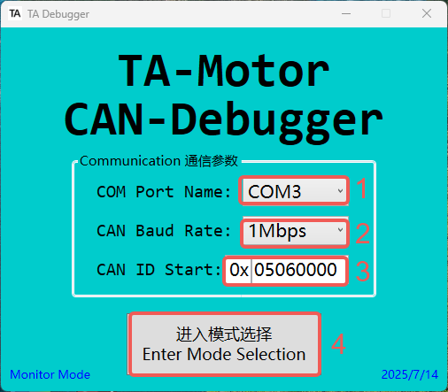
Open TA-Debugger
- Select the correct COM port.
- Select the baud rate. Currently, only 1M is available. More baud rate options will be added through firmware updates in the future.
- Select the correct CAN ID. The default CAN ID from the factory is
0x05060000. - Please enter the mode selection. The date in the bottom right corner indicates the software version date.
Check the Connection
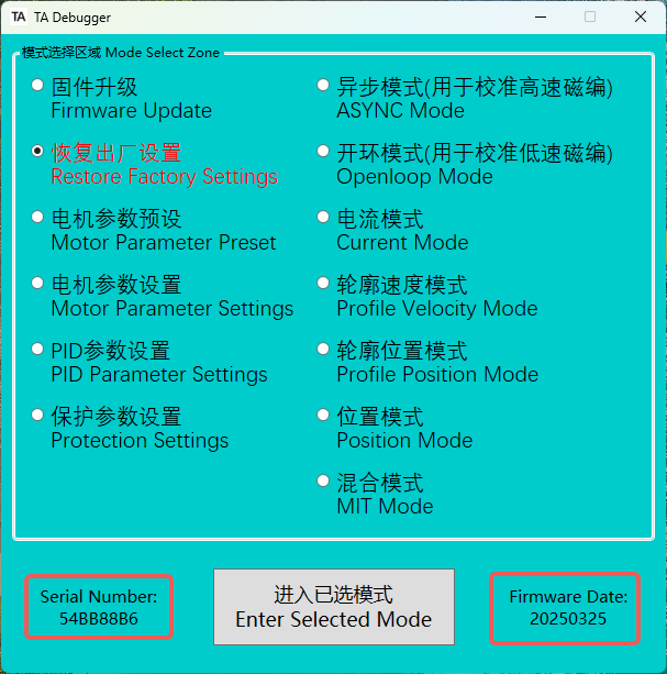
- Check if the serial number and firmware version date are displayed. If displayed, communication is successful; if empty, communication has failed. Please check the wiring and ensure the power is on.
Profile-Position Mode
-
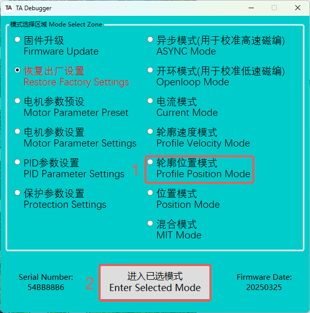
Next, we will activate the actuator using the Profile Position Mode as an example. This mode allows simultaneous control of the motor's phase current limit, speed, and the reducer's position (which can be switched to motor position via motor parameter settings). The Profile Position Mode includes a built-in trajectory planning function, where any updated position commands sent before the completion of the current trajectory will be disregarded.
-
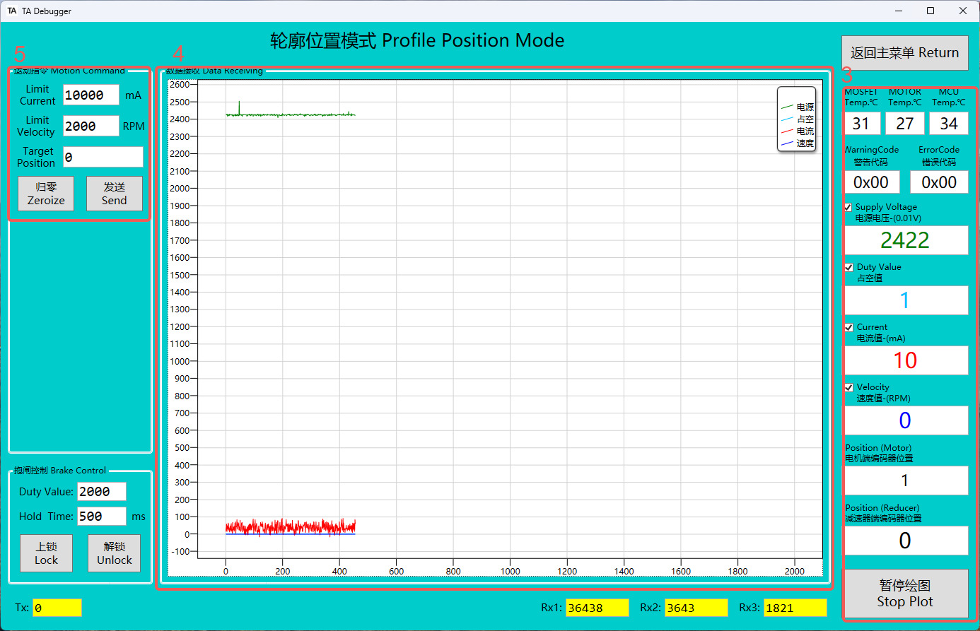
Please enter the selected mode. Once entered, the brake will automatically release, and the LED indicator will turn solid green
-
Real-time actuator status information.
-
Real-time information of voltage, PWM, current, and velocity curves.
-
Control area of this mode
-
After entering profile position mode, the reducer will automatically return to 0 by default. The user can also choose not to auto-reset to 0 in the motor settings.
-
Try entering the position 5000 in this area and click Send. The reducer end will then move to position 5000.
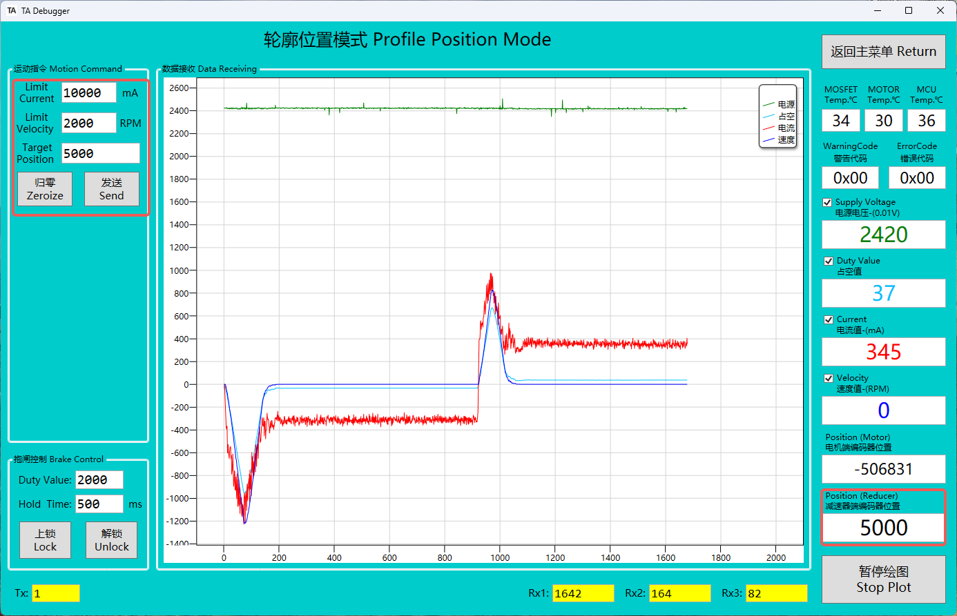 ✅
✅The value for one full rotation of the reducer end is 16 bits = 65536