Hardware wiring
Interface description
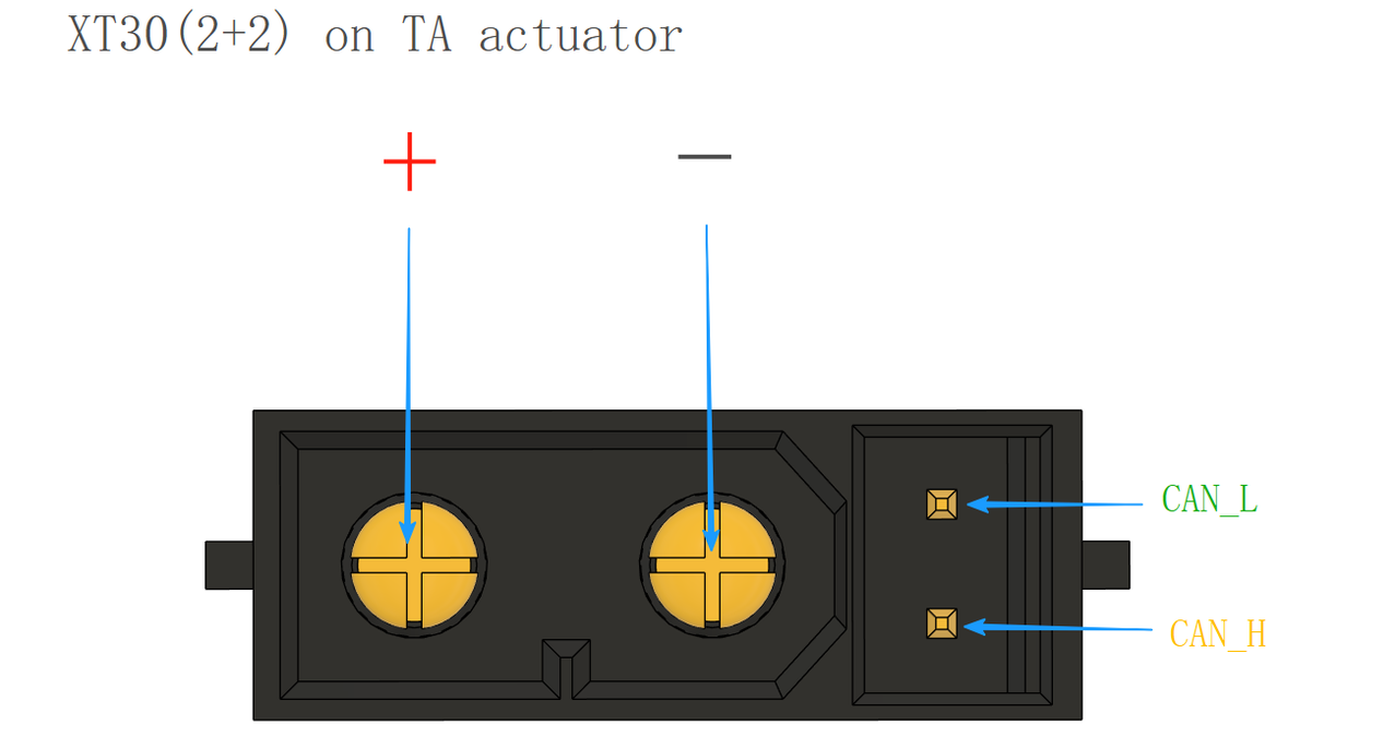
- Power and Communication Adapter Cables: The actuator uses an XT30 (2+2) male connector, with 2 pins for power and 2 pins for signal. It is recommended to use twisted-pair cables for signal transmission.
🍰
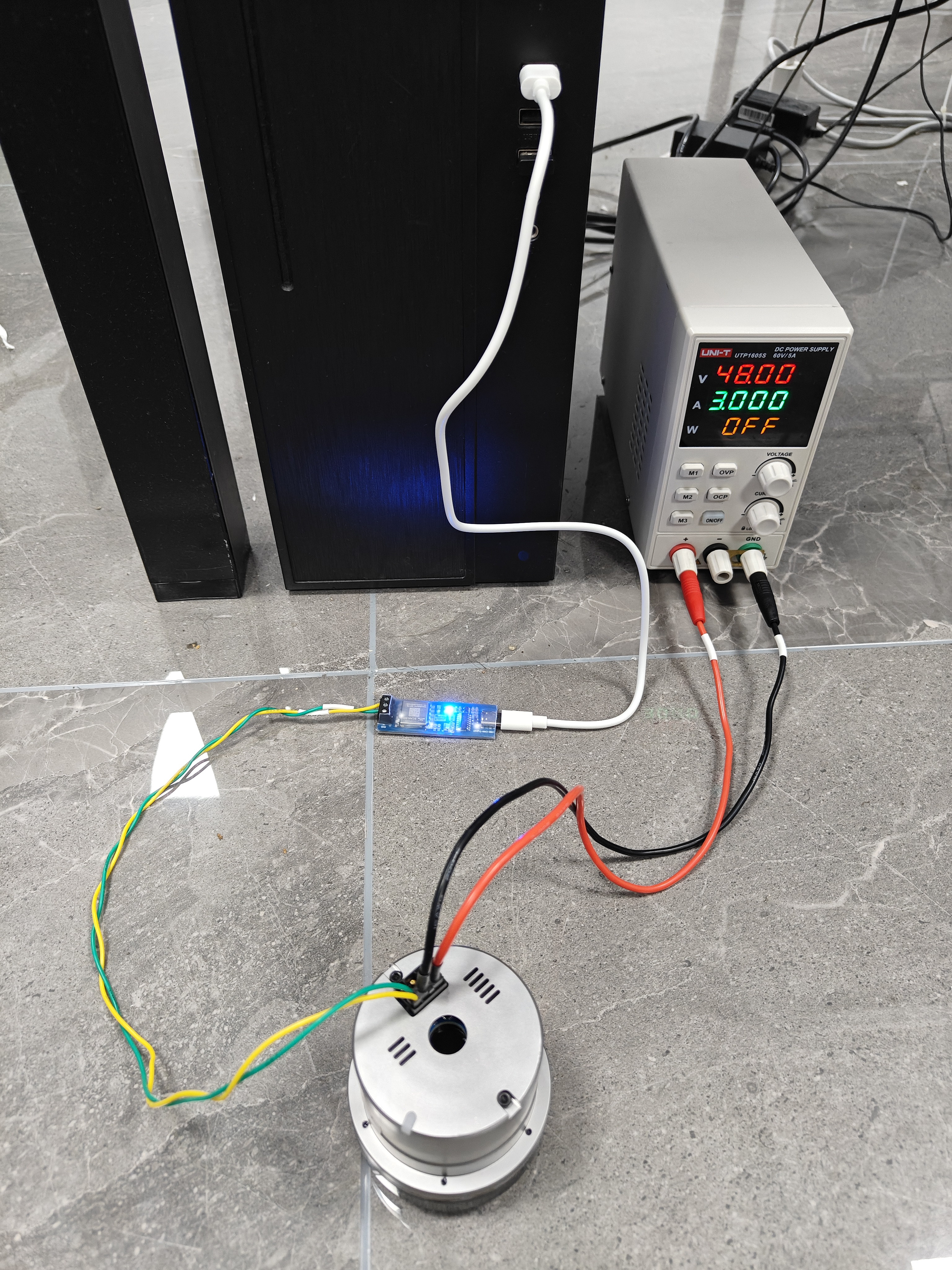
After wiring, please carefully check for any reverse connections, and use a multimeter to test for short circuits. If the power supply polarity is reversed or shorted, the actuator may be damaged.
Actuator wiring method
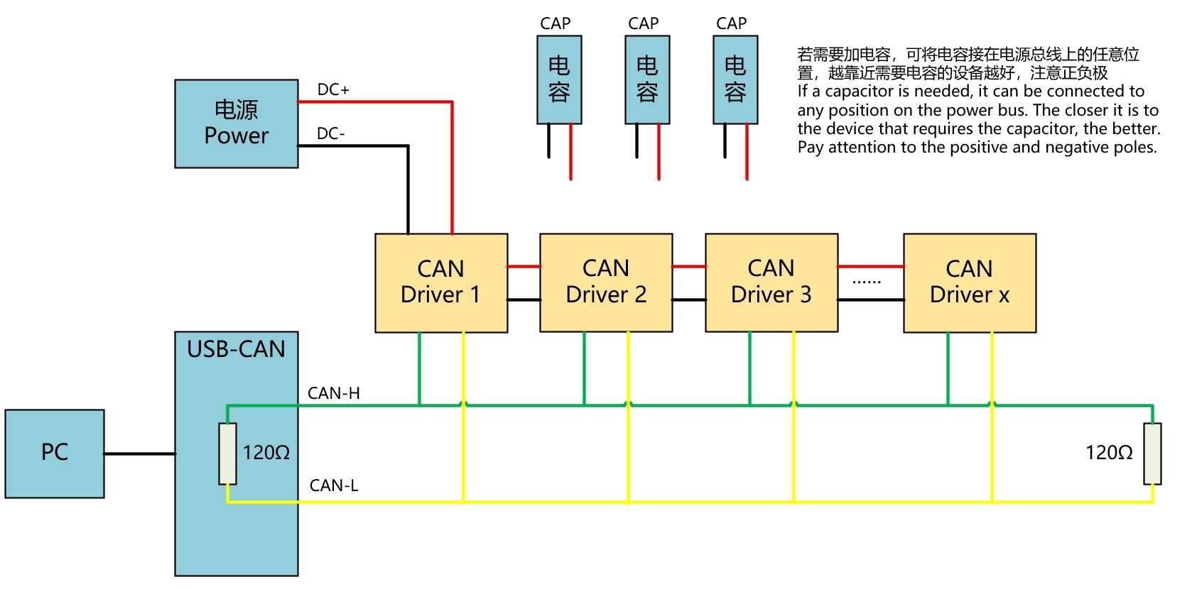
- Actuators with Brakes: When using Profile Position, Position, or MIT modes, if automatic brake engagement upon power-off is required, an external capacitor must be connected. The capacitor size should be determined according to the actual application scenario.
- CAN Bus Termination: According to the CAN communication protocol, a 120 Ω resistor must be connected at both ends of the CAN_L and CAN_H lines.
- Electromagnetic Interference Precautions: If the operating environment has strong magnetic interference, it is recommended to use shielded cables for the CAN communication lines to prevent data transmission errors.