Single Actuator control
Reference video:
Reset
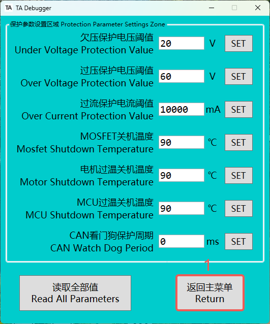
- When need to switch modes, a reset is required. In TA-Debugger, return=reset. After sending the reset command, the driver will immediately restart. During the restart, the red LED will light up briefly, then turn off, followed by the blue LED staying solid.
ASYNC Mode
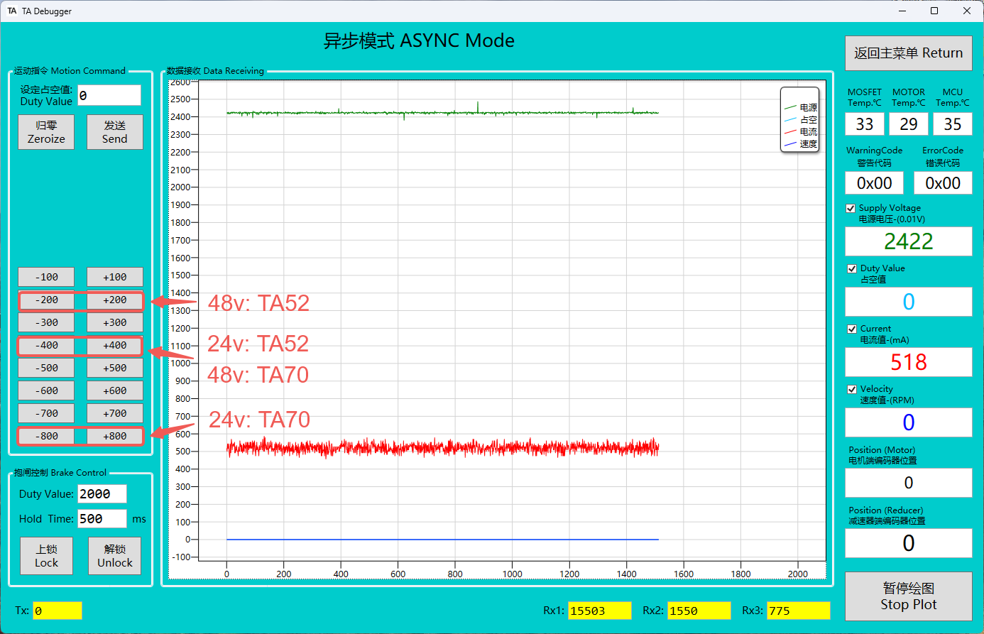
- Asynchronous mode is used during production for calibrating the motor-side encoder, allowing the motor to rotate without relying on sensors.
📌
Under normal actuator conditions, users are advised to avoid using this mode. This mode is primarily provided for remote encoder calibration.
Open-Loop Mode
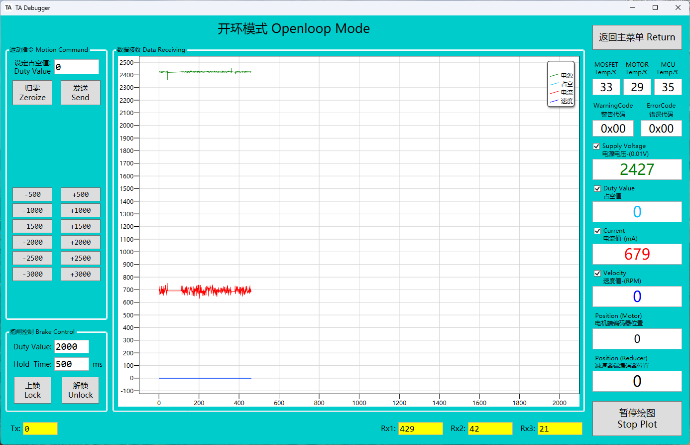
- Open-loop mode is used during production for calibrating the reducer-side encoder, enabling simple motor rotation.
📌
Under normal actuator conditions, users are advised to avoid using this mode. This mode is primarily provided for remote encoder calibration.
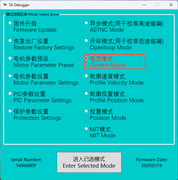
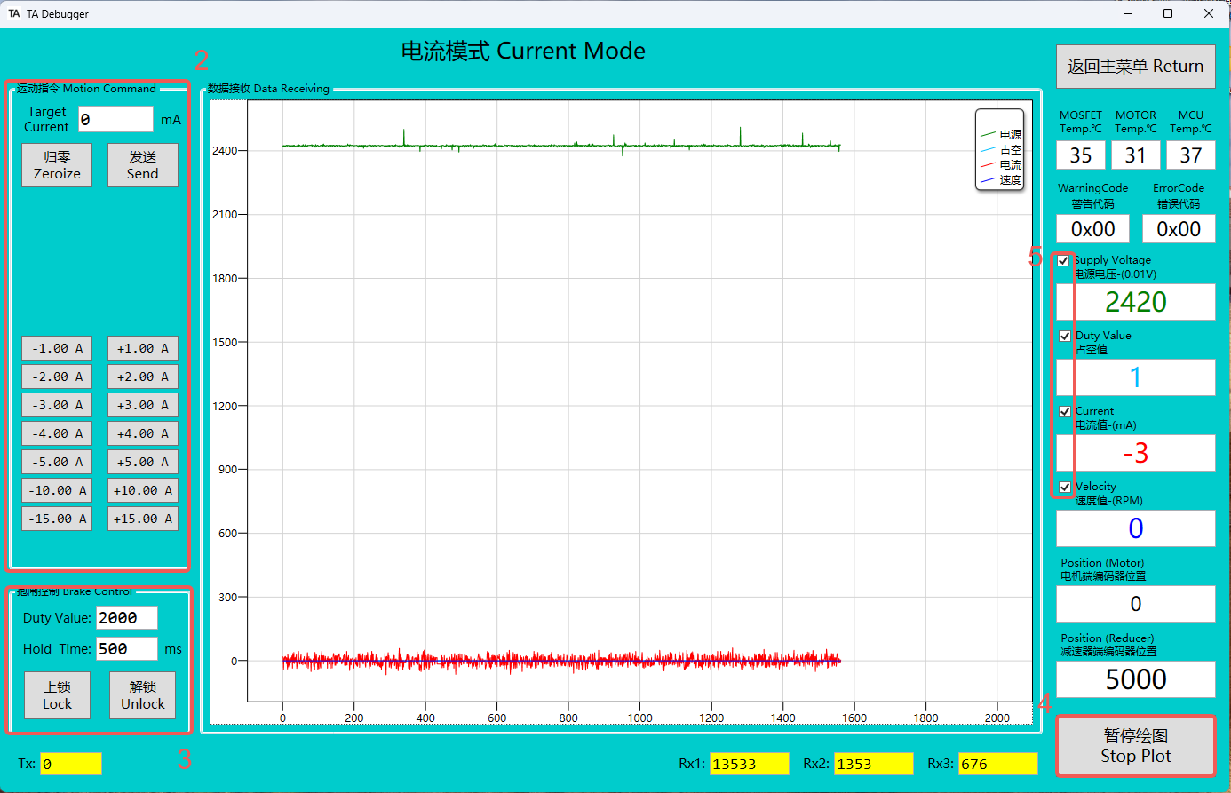
Current Mode
-
After entering current mode, the LED status indicator changes from blue to green, and the brake is automatically released.
-
This area is the control section for current mode. Users can drive the motor by pressing buttons or entering specific current values. When debugging in current mode, please start with a small current and gradually increase it; otherwise, it may cause danger.
-
This area allows manual control of the brake's lock and release states,please do not modify the pwm and duration value.
-
Clicking Stop Plotting will pause the generation of the real-time curve graph.
-
By checking or unchecking the box, you can decide whether to display the corresponding state curve graph.
-
If you need to change the speed of the actuator current regulation, you can modify the current loop pid in this mode once (modify the Flash memory) or in real time (modify the RAM memory). The specific configuration methods can be found in the "Control Frame" section below.
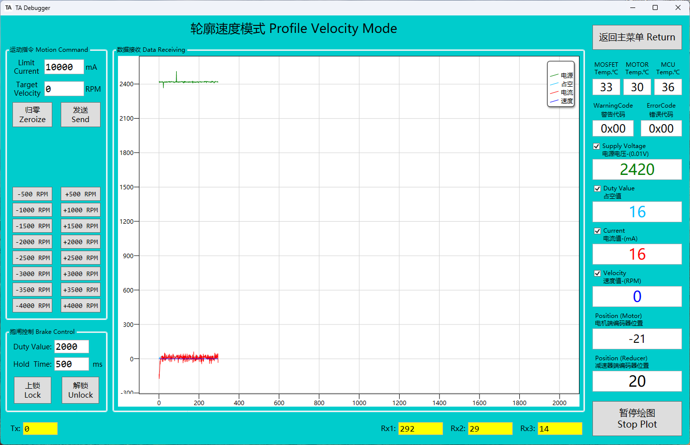
Profile-Velocity Mode
- After entering Profile-Velocity Mode, the LED status indicator changes from blue to green, and the brake is automatically released.
- It is possible to control both the current limit and the motor speed simultaneously. When the current limit is set too low, it may prevent the motor from reaching the desired speed, as the current is insufficient to provide the necessary torque, thus limiting the motor's rotational speed. Therefore, when setting the current limit, it is important to ensure that it meets the motor's load requirements at the target speed to avoid situations where the speed cannot reach the expected value.
- If you want to change the acceleration, you can change the value of "veloity mode acceleration". The veloity loop PID is used to adjust the effect of the actual veloity following the planned veloity trajectory. These can be modified once (flash) or in real time (RAM). The specific configuration methods can be found in the "Control Frame" section below.
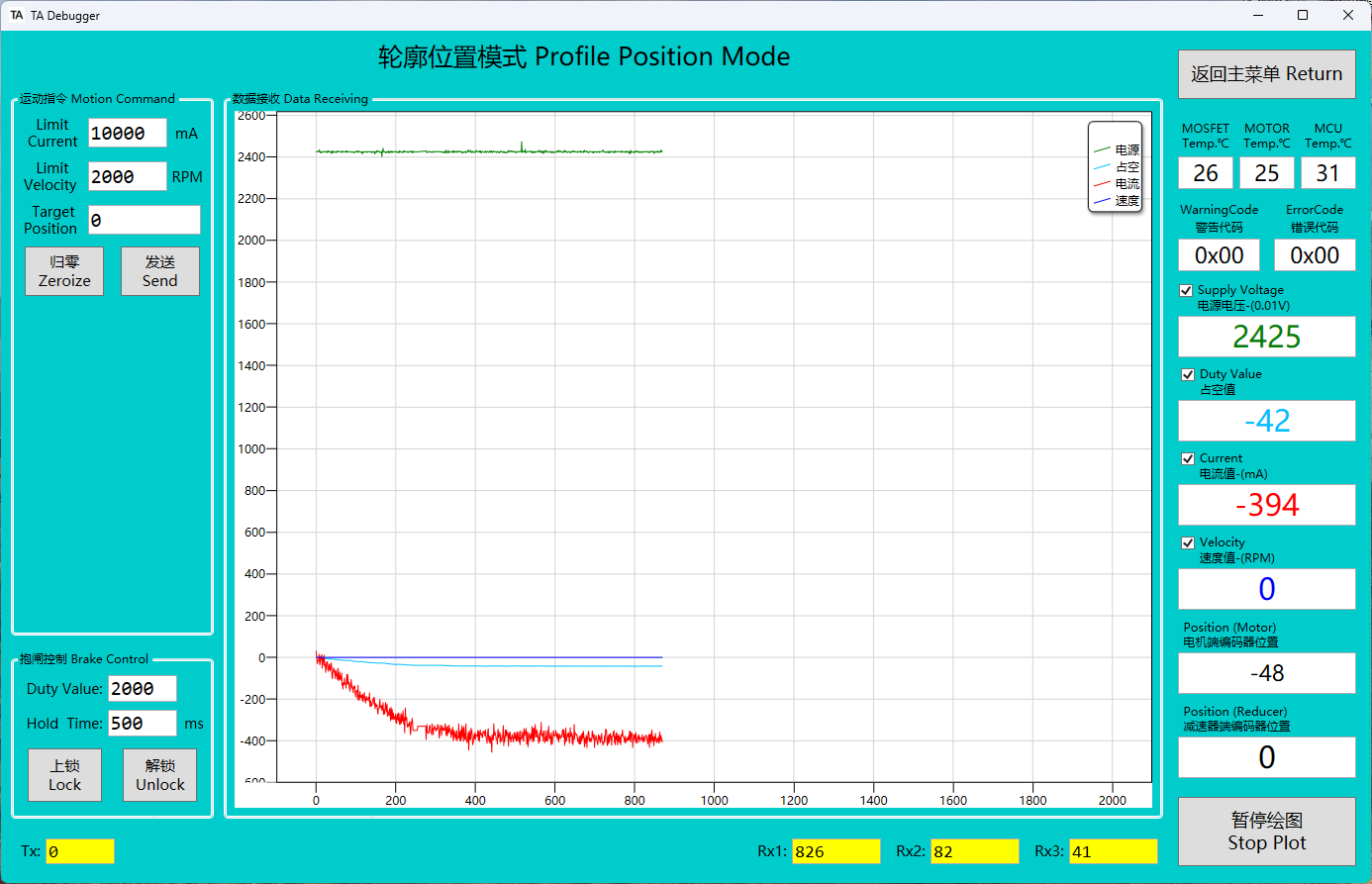
Profile-Position Mode
- Profile position mode has a built-in trajectory planning function, and any position update commands sent before the previous trajectory planning is completed will be ignored. This mode is suitable for large angle control and cannot input position values at high frequency.
- After entering Profile-Position Mode, the LED status indicator changes from blue to green, and the brake is automatically released. The reducer end automatically returns to the zero position (this behavior can be disabled in the motor parameter settings).When exiting, the brake will automatically lock.
- The current limit, motor speed, and gearbox position (can be modified to motor position) can be controlled simultaneously. If the current limit is too low, the motor may not reach the set speed, so ensure the current limit meets the load requirements.
- The acceleration and deceleration parameters in this mode can be adjusted. These parameters share a common data structure with the profile speed mode. Both one-time modification (modify Flash memory) or real-time modification (modify RAM memory) are supported. The detailed configuration method can be found in the Control Frame section.
- The current loop, speed loop and position loop pid in this mode support one-time (modify Flash memory) or real-time modification (modify RAM memory). The detailed configuration method can be found in the Control Frame section below.
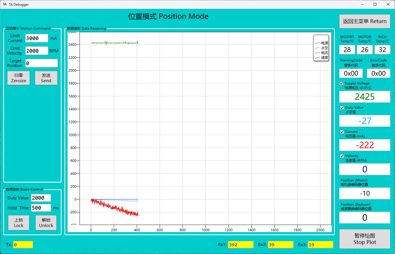
Position Mode
- This position mode uses a three-loop architecture, consisting of position loop, velocity loop, and current loop. Unlike the profile position mode, this mode does not have built-in trajectory planning funtion, so it allows high-frequency position updates. This mode is suitable for controlling small angle changes and is often used for running tracks.
- Upon entering position mode, the LED indicator changes from blue to green, the brake is automatically released, and the reducer returns to position 0 (this auto-reset can be disabled in the motor parameter settings). When exiting the mode, the brake will automatically lock.
- The current limit, motor speed, and gearbox position (can be modified to motor position) can be controlled simultaneously. If the current limit is too low, the motor may not reach the set speed, so ensure the current limit meets the load requirements.
- The acceleration and deceleration parameters in this mode can be adjusted. These parameters share a common data structure with the profile speed mode. Both one-time modification (modify Flash memory) or real-time modification (modify RAM memory) are supported. The detailed configuration method can be found in the Control Frame section.
- The current loop, speed loop and position loop pid in this mode support one-time (modify Flash memory) or real-time modification (modify RAM memory). The detailed configuration method can be found in the Control Frame section below.
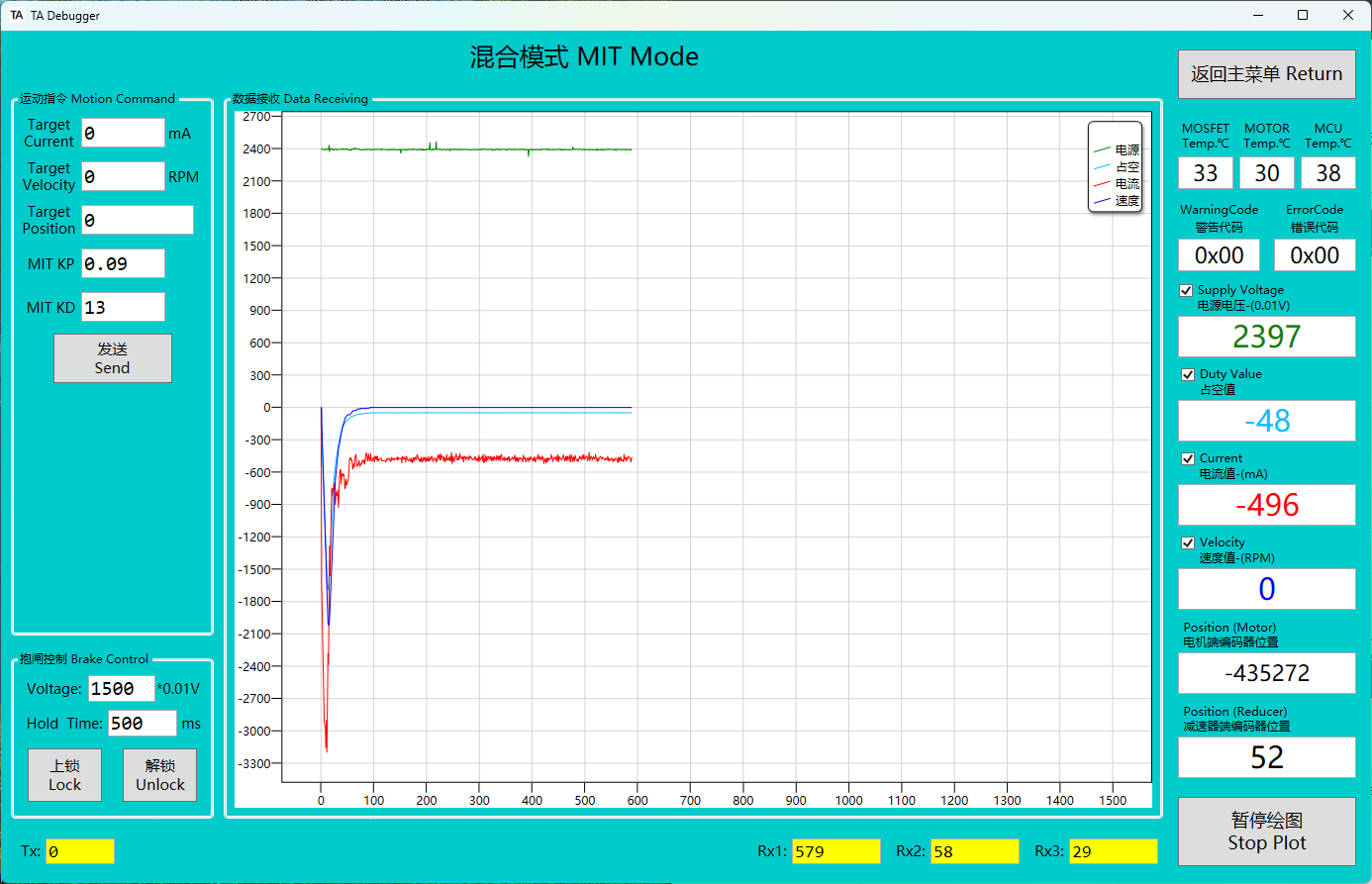
MIT Mode
-
After entering MIT mode, the LED status indicator changes from blue to green, and the brake is automatically released. The reducer end automatically returns to the zero position (this behavior can be disabled in the motor parameter settings).When exiting, the brake will automatically lock.
-
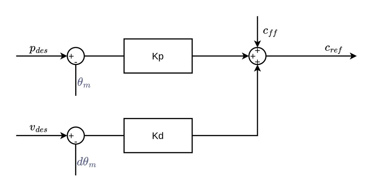
The MIT mode is a specialized control mode developed by MIT, primarily used for precise torque and motor control applications. It allows for advanced control of motor performance.
-
In MIT mode, two separate CAN frames need to be sent: one frame contains the motor's current, speed, and the position information of the reducer (which can be changed to the motor-end position in the motor parameter settings), and the other frame contains the MIT_Kp and MIT_Kd values. The specific method for setting these parameters can be found in the "Control Frame" section below.It is also affected by the current limit value set in the motor parameter settings.
-
Simple Example of MIT Control Mode
Set Position to 0°
Set Position to 360°
Set Velocity to 1000rpm
Set Current to 3A
current
0
0
0
3000
ma
velocity
0
0
1000
0
rpm
position
0
65536
0
0
Kp
0.09
0.09
0
0
Kd
13.1
13.1
30
0