Parameter settings
Reference video:
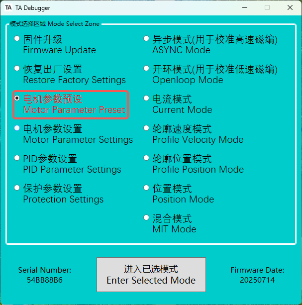
Motor Parameter Preset
-
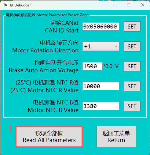
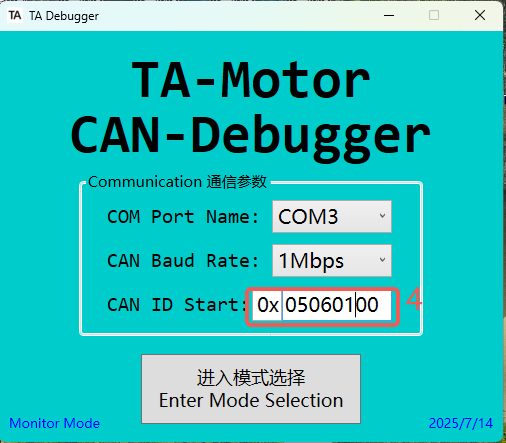
In the motor parameter preset, you can set the CAN ID Start (representing the motor ID) and the motor rotation direction. To set these two values, you must first read all the values.
-
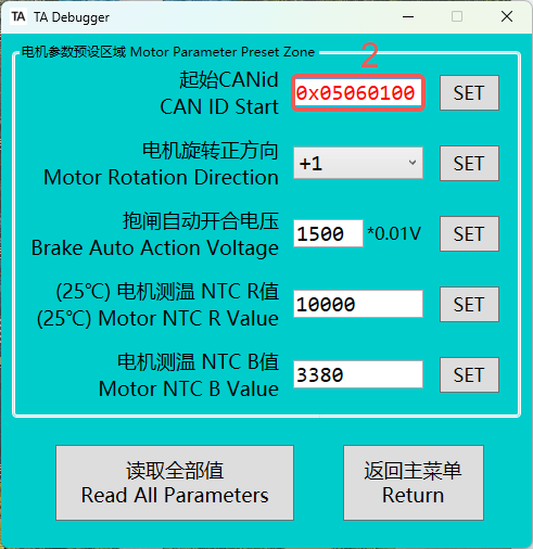
To change motor 0 to motor 1, need to set the CAN ID Start to
0x05060100.Frame ID
05060000Fixed Value
Motor ID
Mode Code
-
After making the changes, click "SET." When the color of the value on the left changes from red to black, it indicates that the settings are complete.

-
When the ID is modified, need to use the new ID value to re-enter TA-Debugger.
-
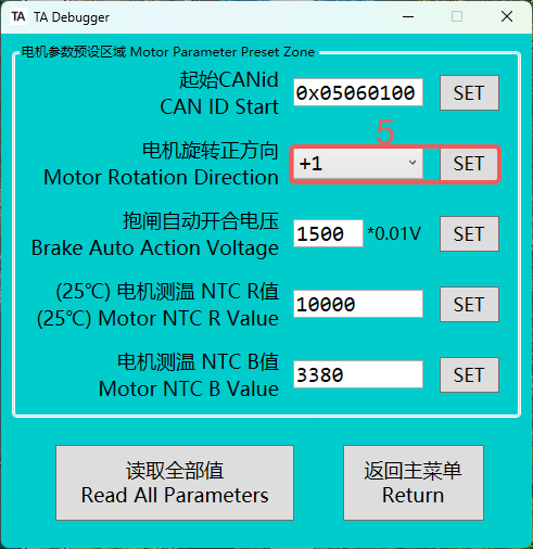
The factory standard for each TA actuator is that counterclockwise rotation is considered positive, and clockwise rotation is considered negative. If you need to change this, simply invert the value for the motor rotation direction.
🚨Once the motor's positive rotation direction is changed, the motor parameter calibration must be performed again.
-
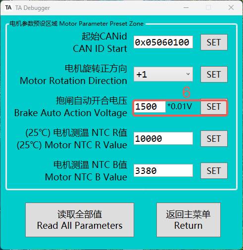
The voltage of the brake input PWM is in units of 0.01V. For example, if the input is 2000, the voltage is 20.00V.
-
The Motor NTC R Value and B Value refer to the resistance value and temperature sensitivity coefficient of the motor side thermistor at 25°C (the B value reflects the characteristic coefficient of the thermistor resistance changing with temperature). The default resistance value of the motor side thermistor at 25°C is 10k, and the B value is 3380.
Generally speaking, users do not need to change these two values.

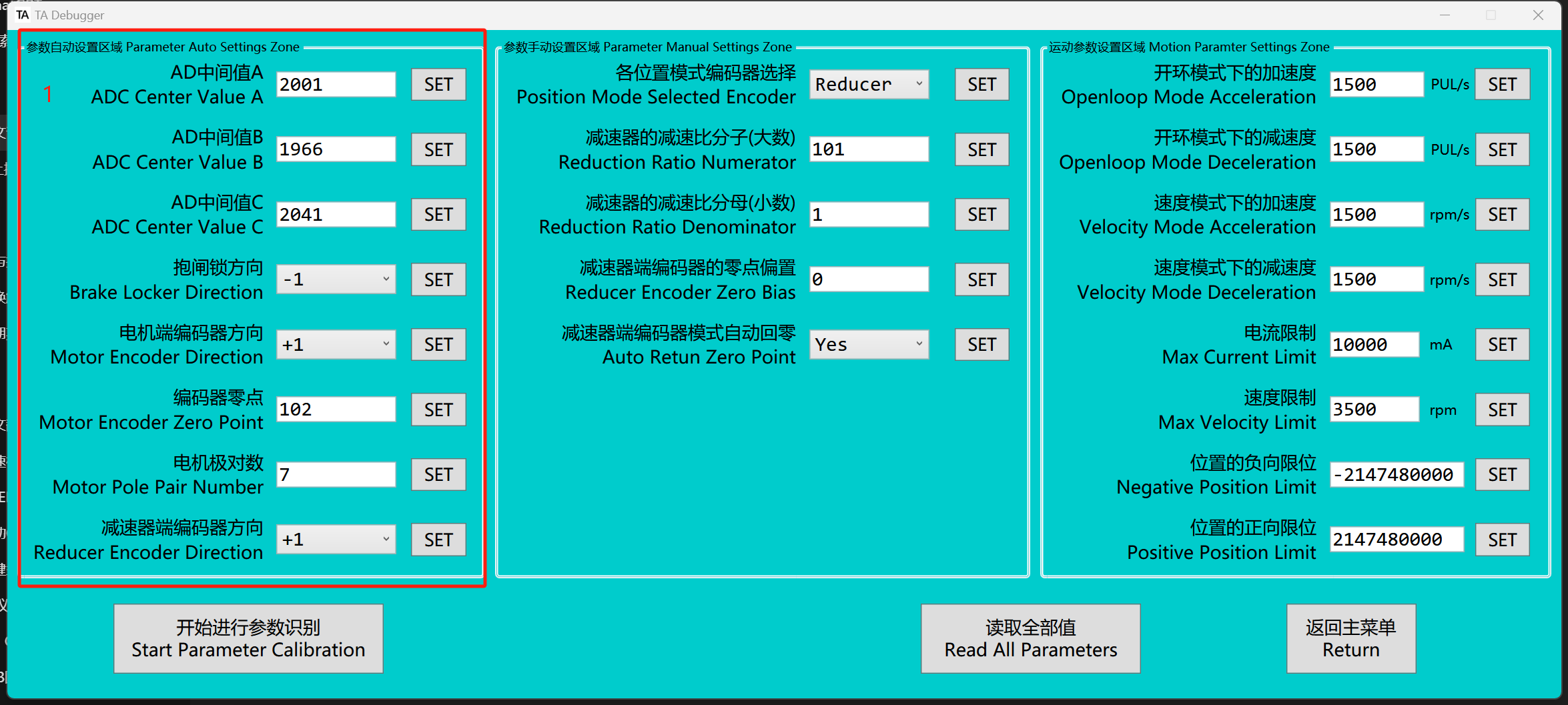
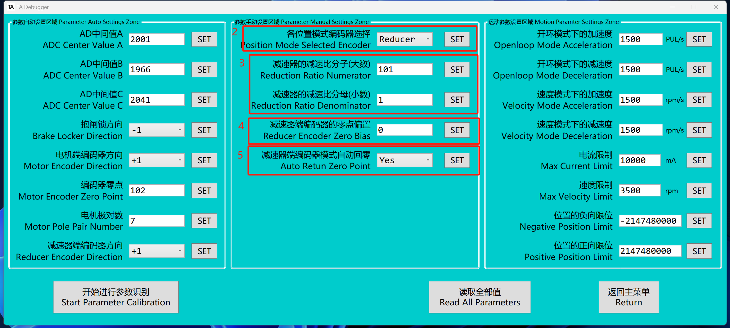
Motor Parameter Settings
The "various position modes" mentioned below refer to: profile position mode, position mode, MIT mode
-
The leftmost column contains the motor parameters for automatic calibration, which generally do not need to be modified. If modification is necessary, please do so under the guidance of a professional.
-
In the "position mode selected encoder" , the default value is Reducer, meaning that in position-related control modes, the position input corresponds to the encoder value at the reducer side, The "Positive (negative) position limit" also sets at the reducer side. If Motor is selected, the position input will correspond to the encoder value at the motor side, the "Positive (negative) position limit" also sets at the motor side.
-
The value of the reduction ratio will be set according to the actual reduction ratio of the gearbox and does not need to be changed by the user.
-
The zero position of the reducer side can be adjusted by modifying the encoder's zero offset. The modification process is as follows: rotate the reducer side to the desired zero position, record the current position value, and write it into the system. If the current zero offset value is not zero, add the recorded value to the existing offset.
-
This parameter determines whether the actuator will automatically return to 0 when entering various position modes.
-
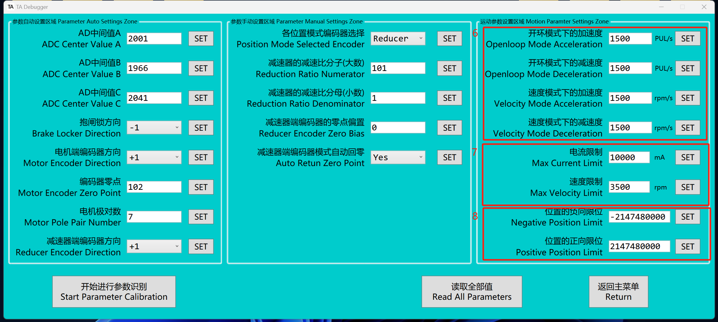
Users can modify acceleration and deceleration parameters in open-loop mode and profile velocity mode, with the values stored in Flash. Real-time adjustment of acceleration and deceleration is also supported in open-loop mode or profile velocity mode, with these adjustments stored in RAM. For real-time modification instructions, please refer to CAN2.0B communication protocol.
✅After power on, if RAM is not written, the values from Flash will be used. If RAM is written, the values from RAM will be used.
The "velocity mode acceleration (deceleration) " also applies to the profile position mode and position mode.
-
Current limiting only takes effect in MIT mode. The current limit affects acceleration under non-stall conditions and torque under stall conditions. The speed limit value restricts the motor speed in profile velocity,profile position, position mode.
-
Users can set the positive and negative limit of the motor or reducer end according to the "position mode selection encoder".
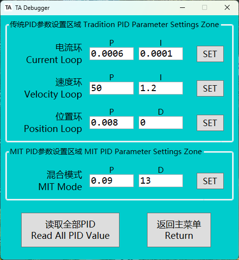
PID Parameter Settings
- Users can configure various PID parameters in this interface for one-time settings, with the values stored in Flash. Real-time PID parameter adjustment is also supported, with these values stored in RAM. For detailed instructions, please refer to the "CAN Frame Introduction" section below.
✅
When the system is powered on for the first time, if no values are written to RAM, the values from flash memory will be used. If values are written to RAM, the system will use the values from RAM.