Hardware Preparation
Packing List
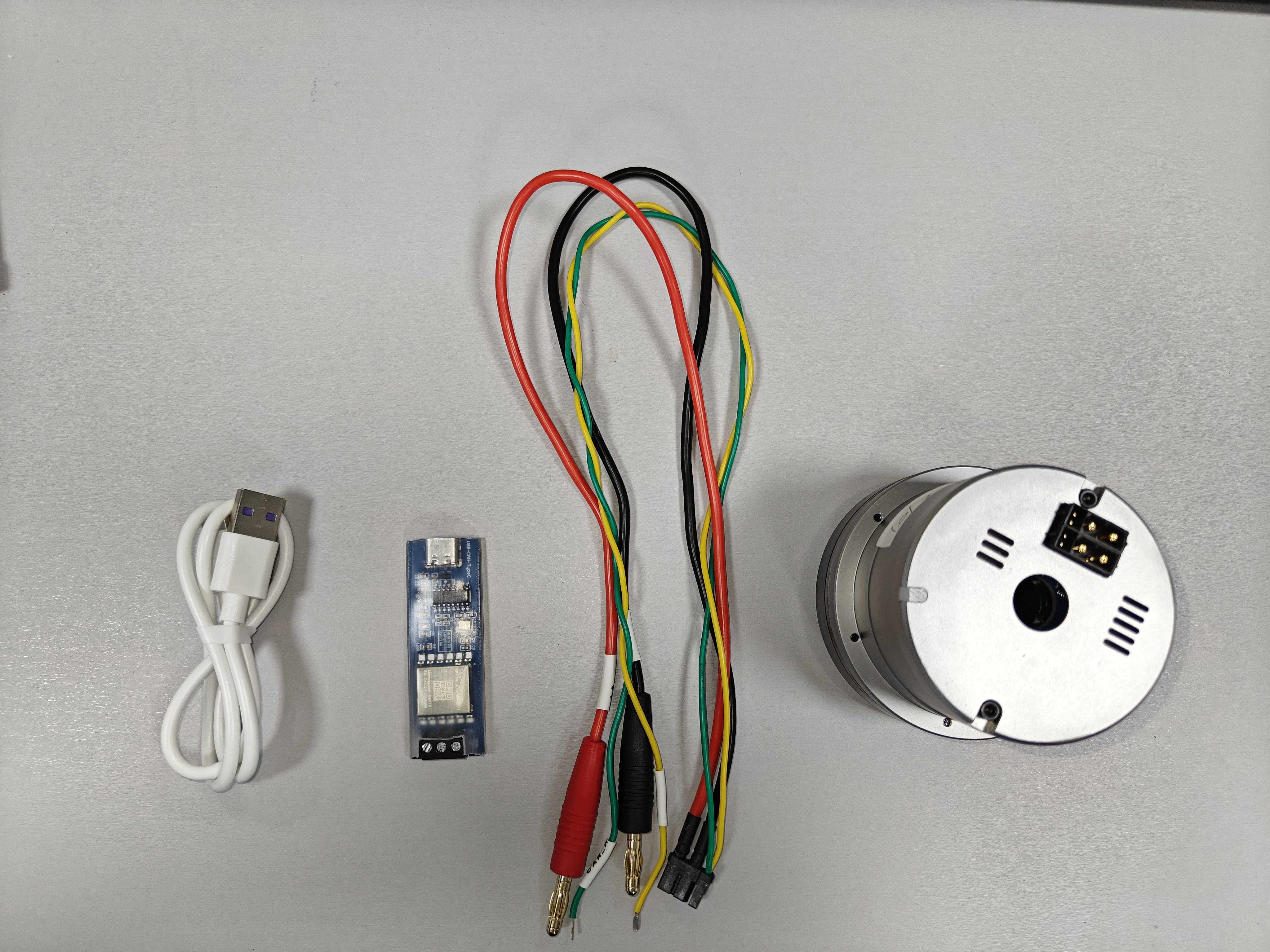
- The package includes the actuator and a debugging cable kit. The debugging kit consists of a USB-to-CAN adapter, Type-C cable, power cable, and communication cable. For first-time orders, our company provides one complimentary debugging kit; additional kits need to be purchased separately.
- The actuator comes with a one-year warranty covering non-human-induced damages.
Required Tools and Accessories
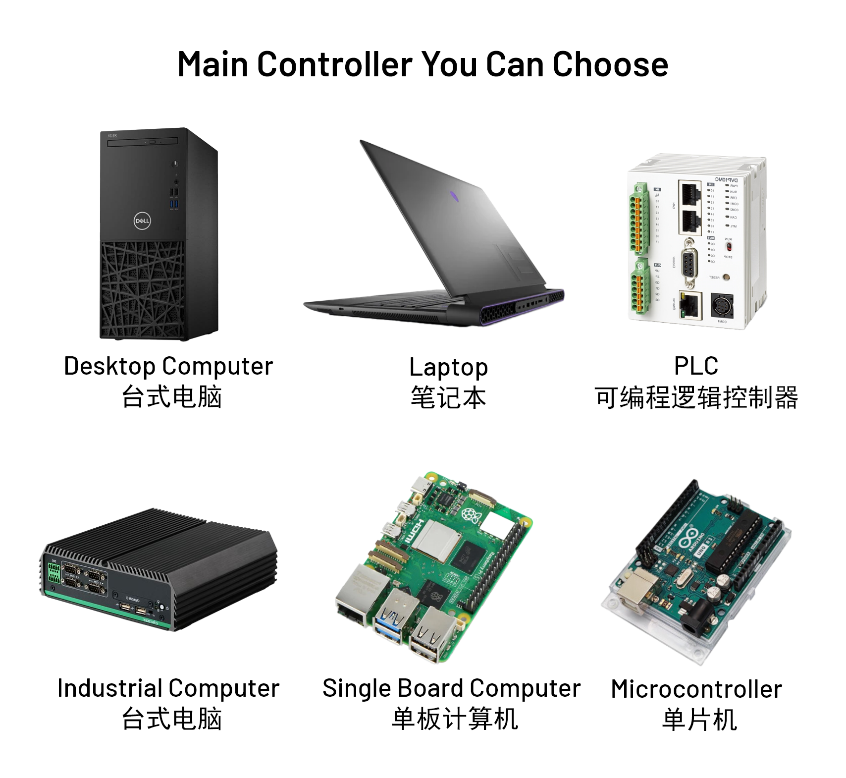
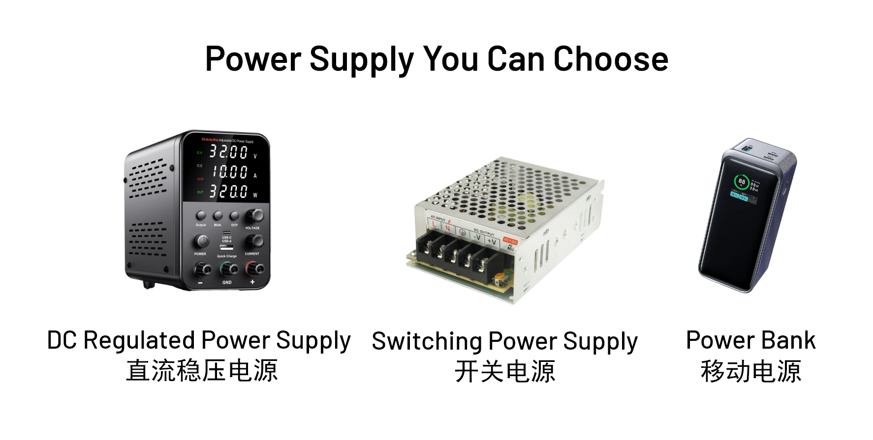
In addition to the items included in the shipment, controlling the actuator also requires a host controller (such as a computer, industrial PC, microcontroller, Raspberry Pi, or PLC that supports CAN or USB communication) and a power supply (DC regulated power supply, switching power supply, or portable power bank).
(1) Power Supply Requirements and Selection Recommendations
- Voltage and Current: Refer to the Product Overview for the rated voltage and current requirements. It is recommended to use a power supply with current or power monitoring to prevent unexpected issues during operation. For driving a single TA actuator with a 24–48V DC regulated power supply, a bus current of 5A is sufficient.
- Actuator Model Selection: Refer to the Product Overview and select an appropriate model based on torque, power consumption, dimensions, precision, and supply voltage.
Common supporting equipment
(1) Adapter board
XT30(2+2) to GH1.25(10Pin)
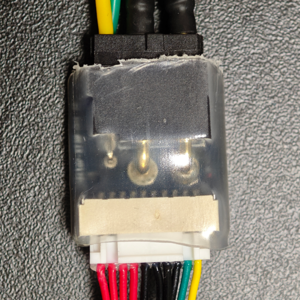
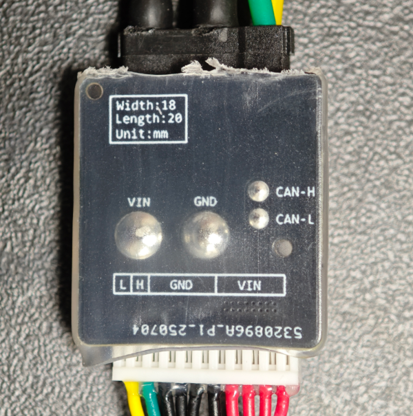
Applicable to TA40 series interface
(2) CAN related
USB-USART-CAN
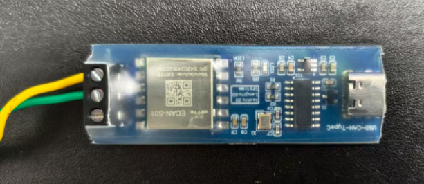
The factory-configured baud rate is 921600 baud by default, and the board has a 120Ω resistor.
USB-CAN
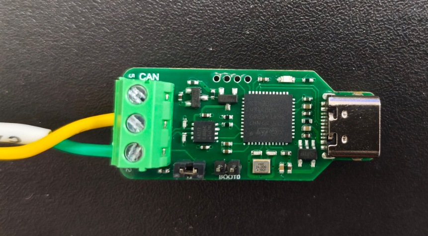
Compatible with various baud rates, 921600 baud rate is recommended to adapt to the host computer software. The jumper cap can be selected to connect to the 120Ω resistor or the boot0 pin.
TTL-CAN
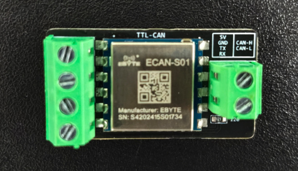
This converter is designed for devices that need to convert USART to CAN. Common use cases include MCUs, PLCs, and other edge computing units. This converter requires a 5V power supply and has an onboard 120Ω resistor.