TA-Debugger User Guide
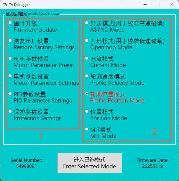
Interface Introduction
- The area on the left is the parameter configuration area. It is recommended to use this software to configure the parameters of the TA actuator, rather than using messages. This is a very reliable and efficient method.
- The area on the right is the motion control area, used for basic joint motion debugging.
Firmware Update
-
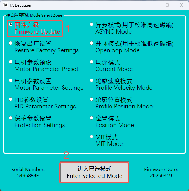
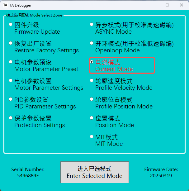
Select Firmware Upgrade Mode.
-
Enter firmware upgrade mode, and the LED indicator will turn solid green.
-
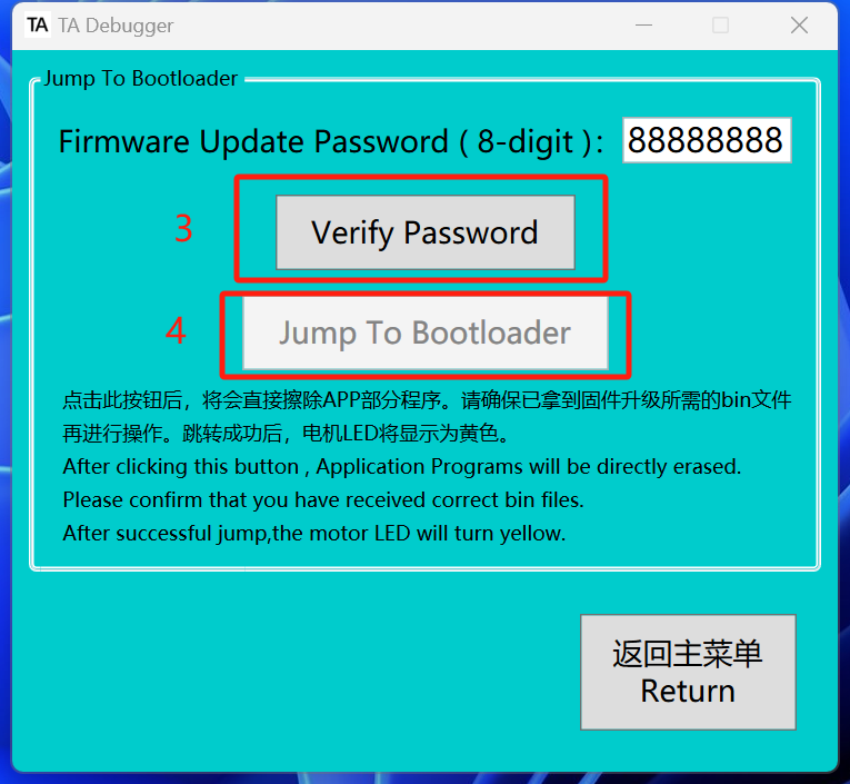
Verify the password. The password is 88888888.
-
Enter to the bootloader.
-
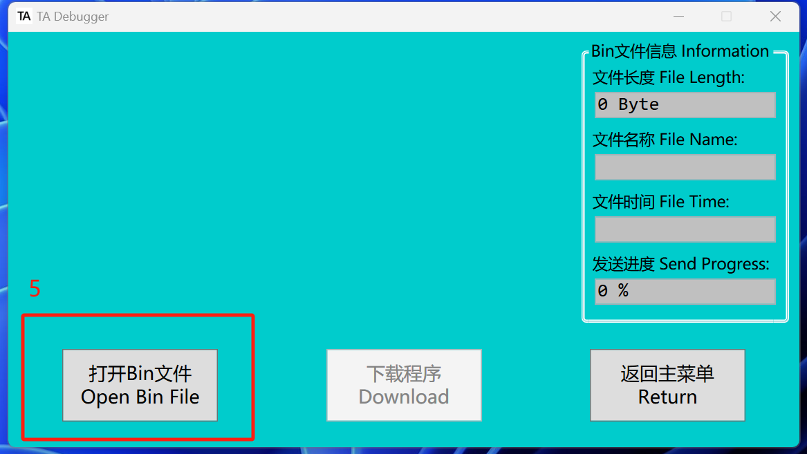
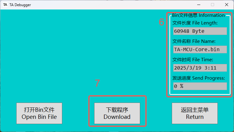
After entering the bootloader, the LED indicator will turn orange. Once the LED status is confirmed to be correct, click to open the Bin file and select the latest version of the Bin file based on the date. The Bin file can be downloaded from the official link or obtained by contacting the relevant technical personnel.
-
After opening the Bin file, please check the file name and date.

-
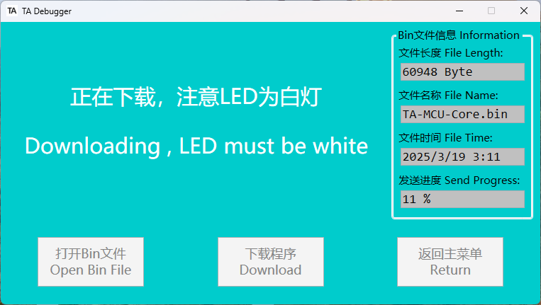
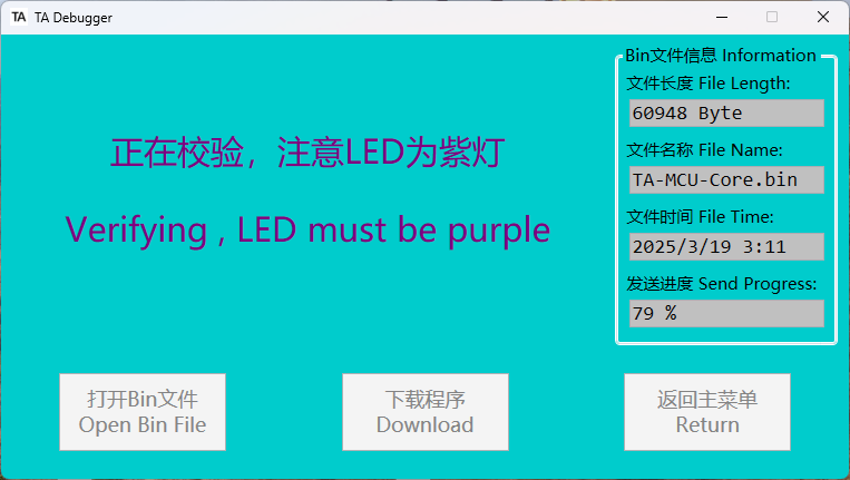
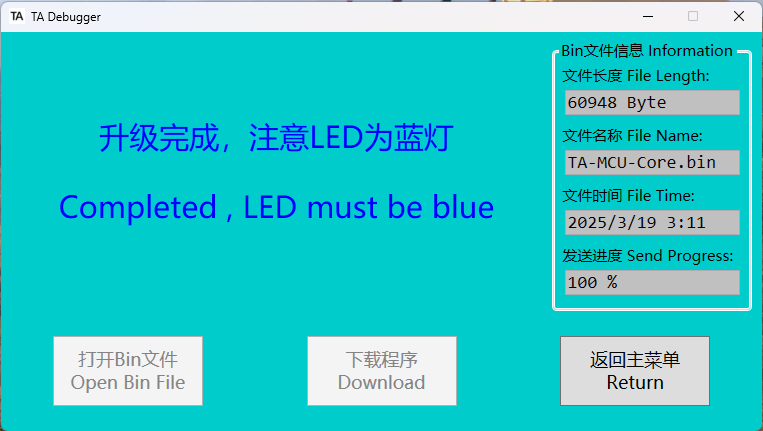
After clicking "Download Program," the downloading process will begin immediately. The progress is indicated by three different LED colors: white represents the downloading process, purple represents verification, and blue indicates the download is complete.
💡Please note that you should observe the LED color on the actuator, not the font color in the software.
-
Once the download is complete, return to the main menu.
Restore Factory Settings
-
If the firmware update causes changes to the original EEPROM/Flash content (there will be instructions in the change.txt file), it will be necessary to perform a factory reset and motor parameter calibration.
-
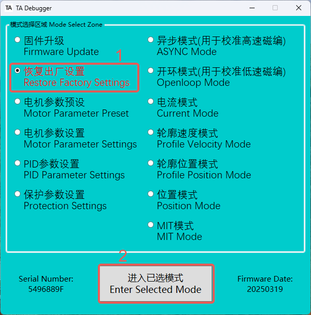
After selecting "Restore Factory Settings," please enter the selected mode. Once entered, the LED indicator will turn solid green.
-
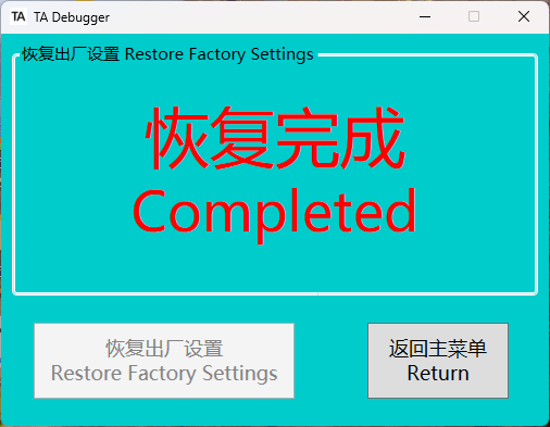
After clicking "Restore Factory Settings," a successful reset will prompt a "Restore Completed" message. If the reset fails, an error message will be displayed. Note that after restoring factory settings, the CAN ID will reset to its default value of
0x05060000. If the previous CAN ID was not0x05060000, you will need to close the software, re-enter the correct CAN ID, and then access the software again.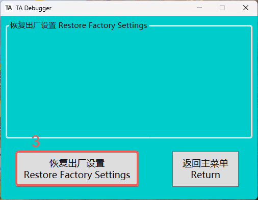
Motor Parameter Calibration
-
After restoring the factory settings, the encoder zero position will change, which may cause the actuator to malfunction. Therefore, it is necessary to enter the motor parameter setting mode to calibrate the motor parameters. As a result, after restoring the factory settings, motor parameter recognition must be performed to recalibrate the encoder zero position.
-
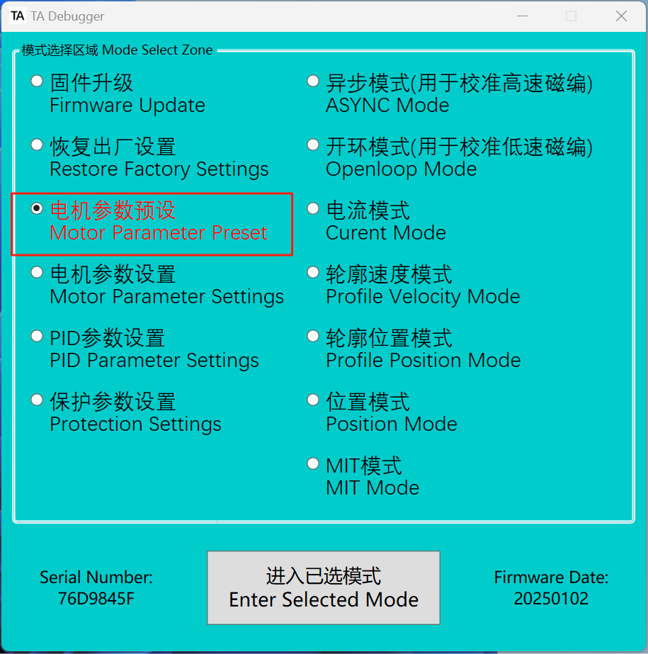
After selecting the motor parameter setting mode, please enter the selected mode. The LED indicator will turn solid green.
-
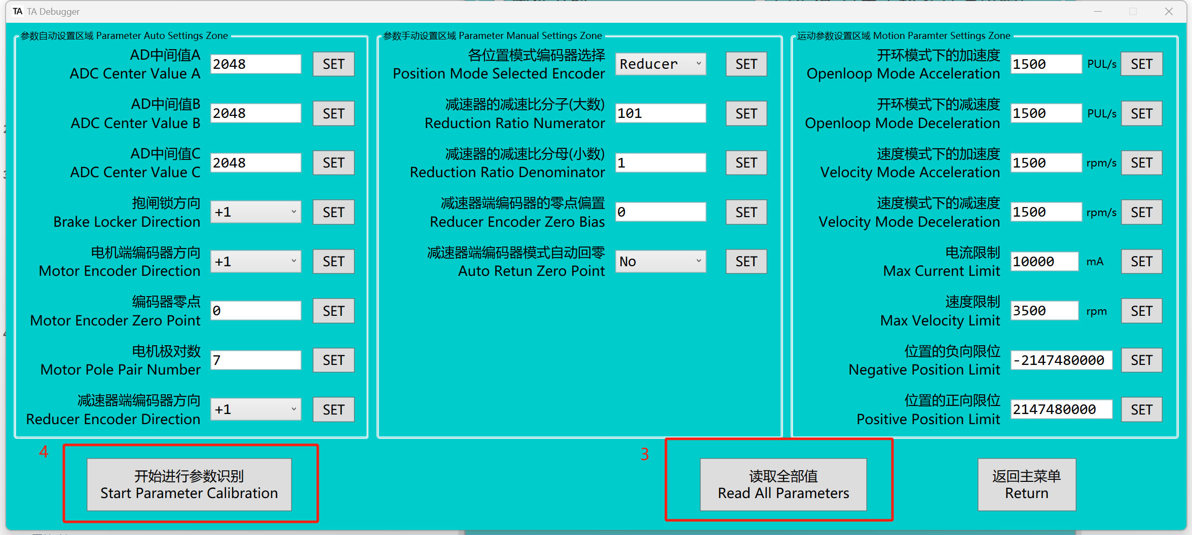
Read all paraments.
-
At this point, ensure the reducer output is unloaded before proceeding with parameter calibration. If there is a load on the output, calibration is likely to fail. Incorrect encoder zero-point calibration will render the actuator non-operational.
✅The values that have not started recognition will be displayed in red, while the values that have been successfully recognized will be displayed in black.

-
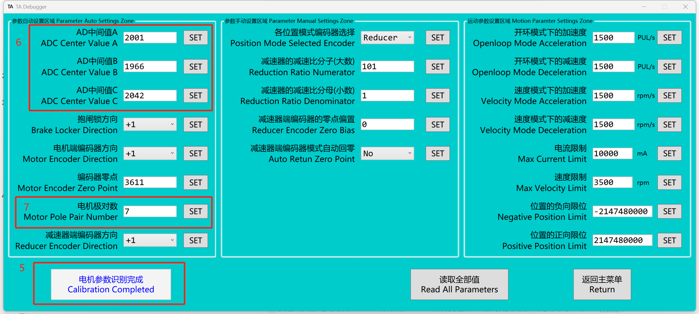
Once the message indicates that the motor parameter calibration is complete, the process is finished.
-
The AD mid-range values A/B/C for TA52 and TA70 should be recognized within the 2048 ± 100 range. If they fall outside this range, it indicates a hardware fault. Please contact the relevant technical personnel for assistance.
-
The motor pole pairs recognized for TA52 should be 7, and for TA70, the pole pairs should be 10. If the values are different, it indicates a hardware fault. Please contact the relevant technical personnel for assistance.
Motor Parameter Preset
-
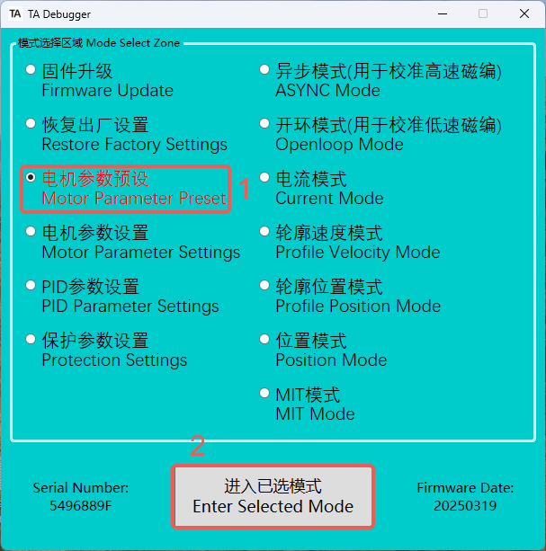
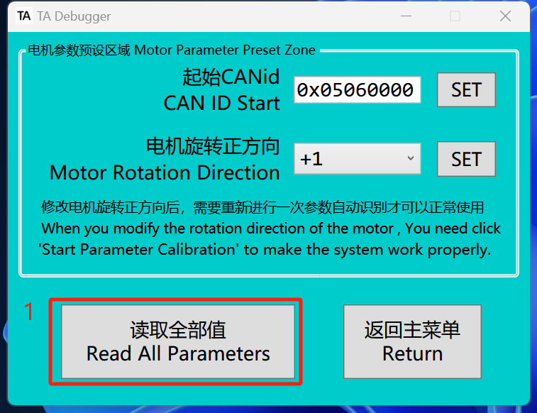
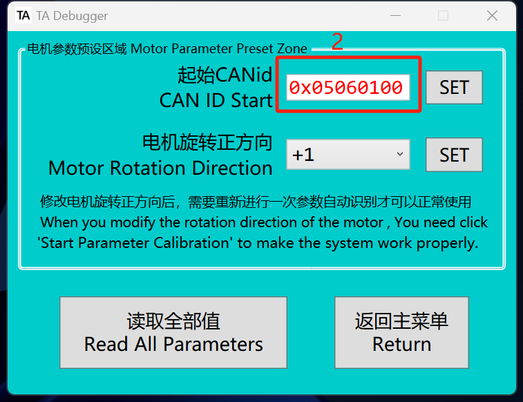
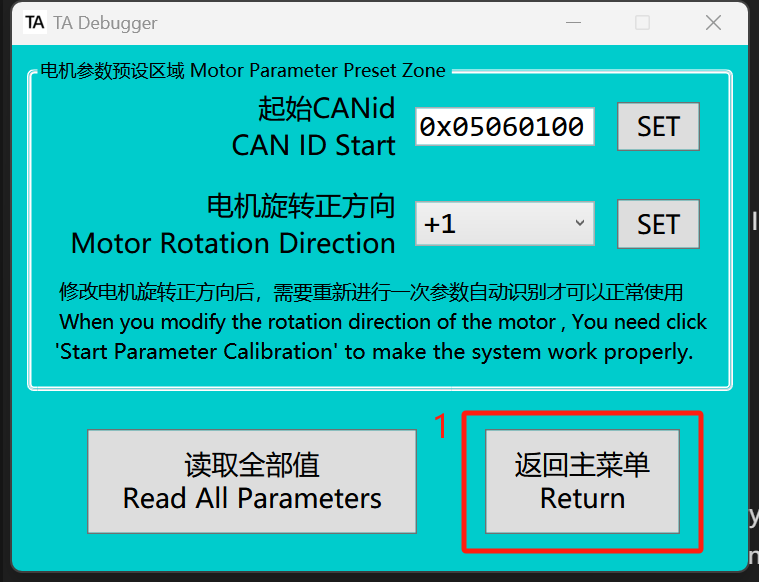
In the motor parameter preset, you can set the CAN ID Start (representing the motor ID) and the motor rotation direction. To set these two values, you must first read all the values.
-
To change motor 0 to motor 1, need to set the CAN ID Start to
0x05060100.Frame ID
05060000Fixed Value
Motor ID
Mode Code
-
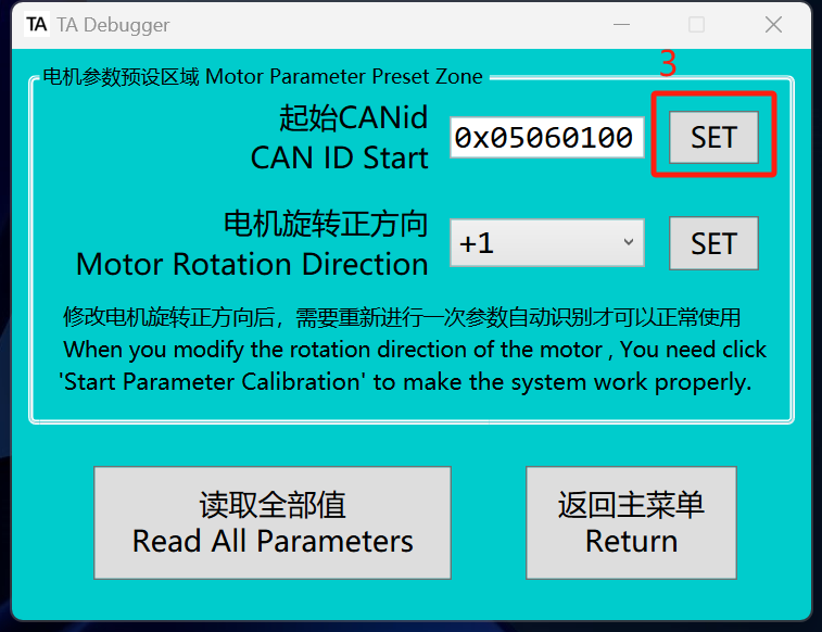
After making the changes, click "SET." When the color of the value on the left changes from red to black, it indicates that the settings are complete.
-
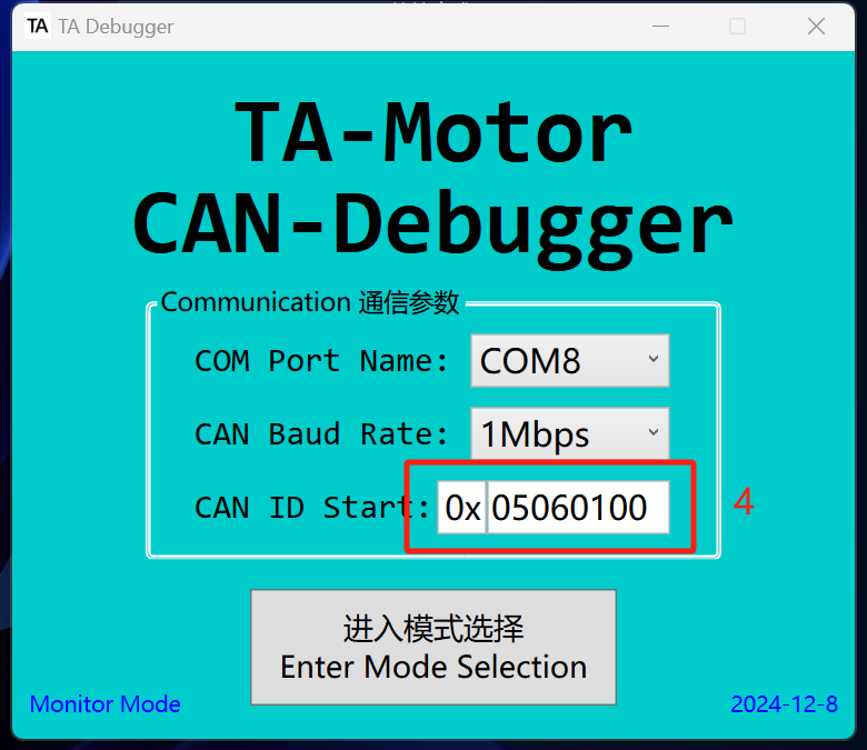
When the ID is modified, need to use the new ID value to re-enter TA-Debugger.
-
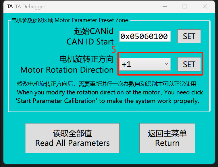
The factory standard for each TA actuator is that counterclockwise rotation is considered positive, and clockwise rotation is considered negative. If you need to change this, simply invert the value for the motor rotation direction.
🚨Once the motor's positive rotation direction is changed, the motor parameter calibration must be performed again.
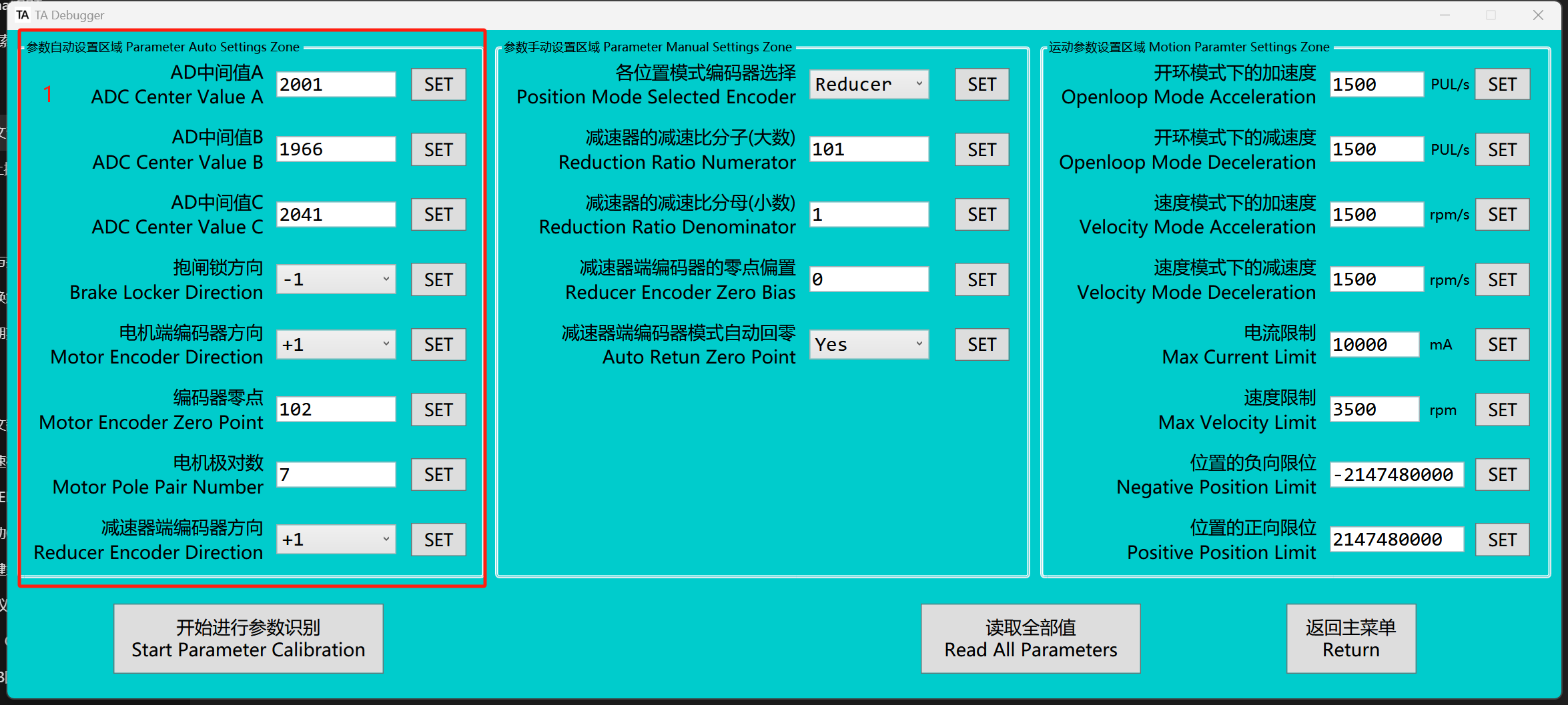
Motor Parameter Settings
-
The leftmost column contains the motor parameters for automatic calibration, which generally do not need to be modified. If modification is necessary, please do so under the guidance of a professional.
-
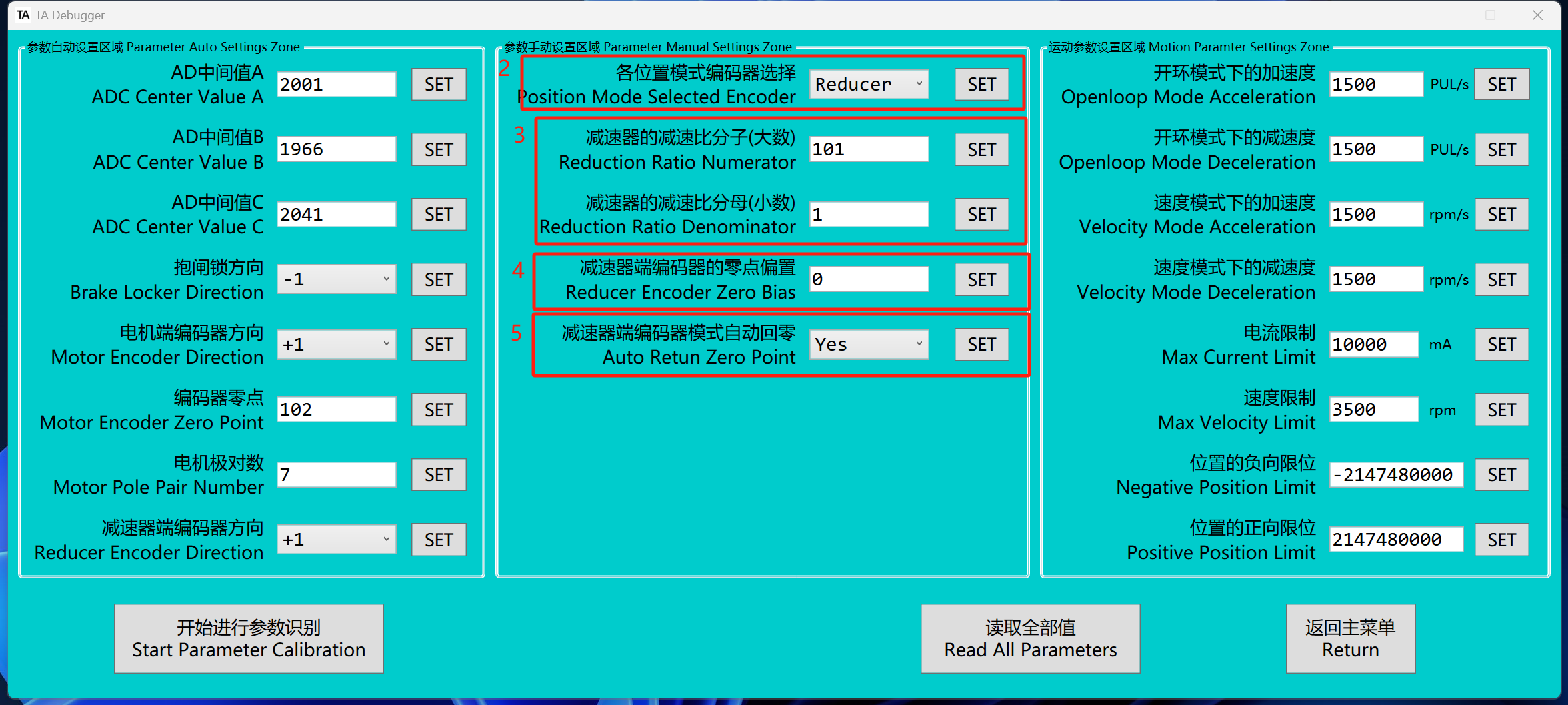
In the encoder selection for position mode, the default value is Reducer, meaning that in position-related control modes, the position input corresponds to the encoder value at the reducer side. If Motor is selected, the position input will correspond to the encoder value at the motor side.
-
The value of the reduction ratio will be set according to the actual reduction ratio of the gearbox and does not need to be changed by the user.
-
The zero position of the reducer side can be adjusted by modifying the encoder's zero offset. The modification process is as follows: rotate the reducer side to the desired zero position, record the current position value, and write it into the system. If the current zero offset value is not zero, add the recorded value to the existing offset.
-
Users can choose whether to automatically return to zero when entering various position modes.
-
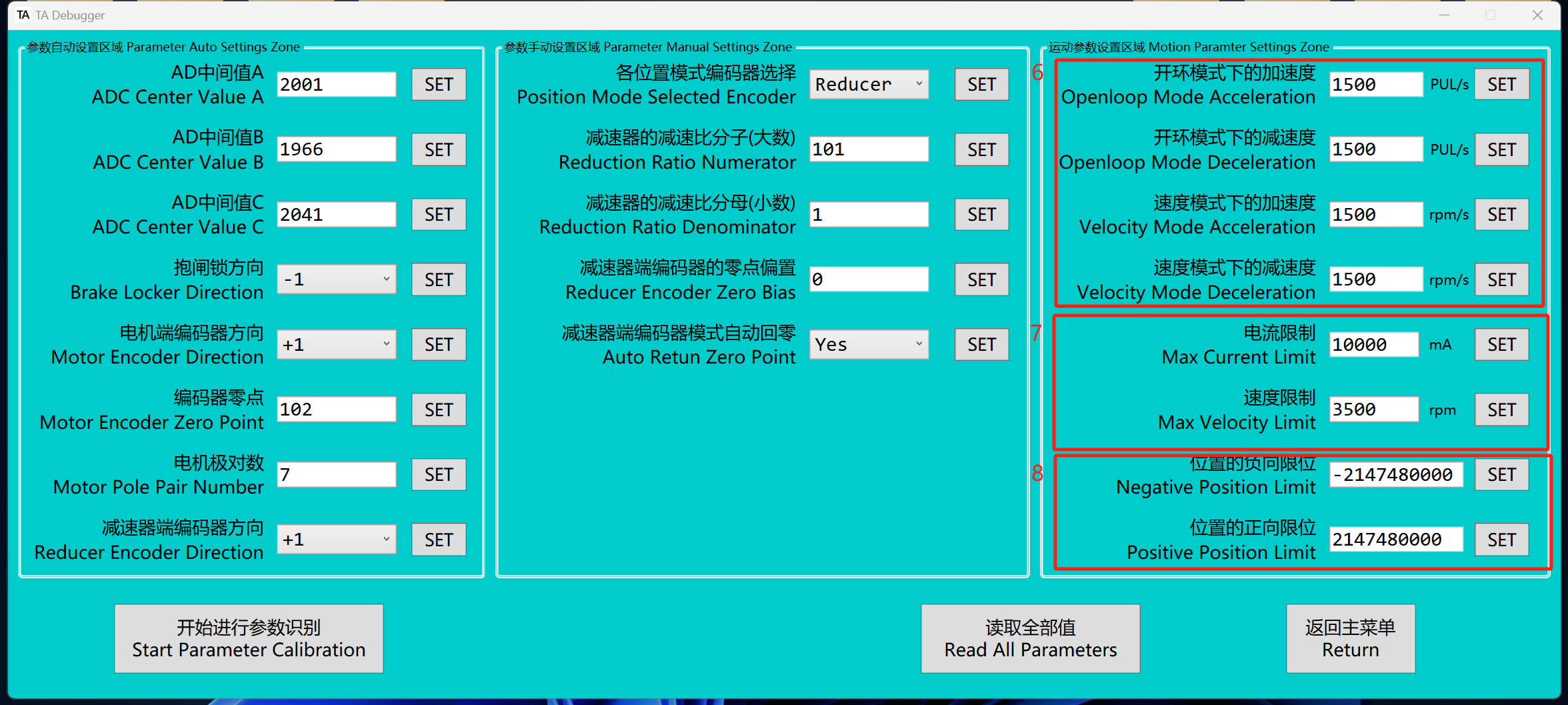
Users can modify acceleration and deceleration parameters in open-loop mode and profile velocity mode, with the values stored in Flash. Real-time adjustment of acceleration and deceleration is also supported in open-loop mode or profile velocity mode, with these adjustments stored in RAM. For real-time modification instructions, please refer to the "CAN Frame Introduction" section below.
✅On the first power-up, if RAM is not written, the values from Flash will be used. If RAM is written, the values from RAM will be used.
The "velocity mode acceleration (deceleration) " also applies to the profile position mode
-
Current limiting only takes effect in MIT mode. The current limit affects acceleration under non-stall conditions and torque under stall conditions. The speed limit value restricts the motor speed in all control modes.
-
Users can set the positive and negative limit of the motor or reducer end according to the "position mode selection encoder".
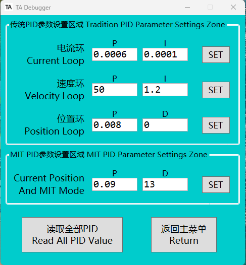
PID Parameter Settings
- Users can configure various PID parameters in this interface for one-time settings, with the values stored in Flash. Real-time PID parameter adjustment is also supported, with these values stored in RAM. For detailed instructions, please refer to the "CAN Frame Introduction" section below.
✅
When the system is powered on for the first time, if no values are written to RAM, the values from flash memory will be used. If values are written to RAM, the system will use the values from RAM.
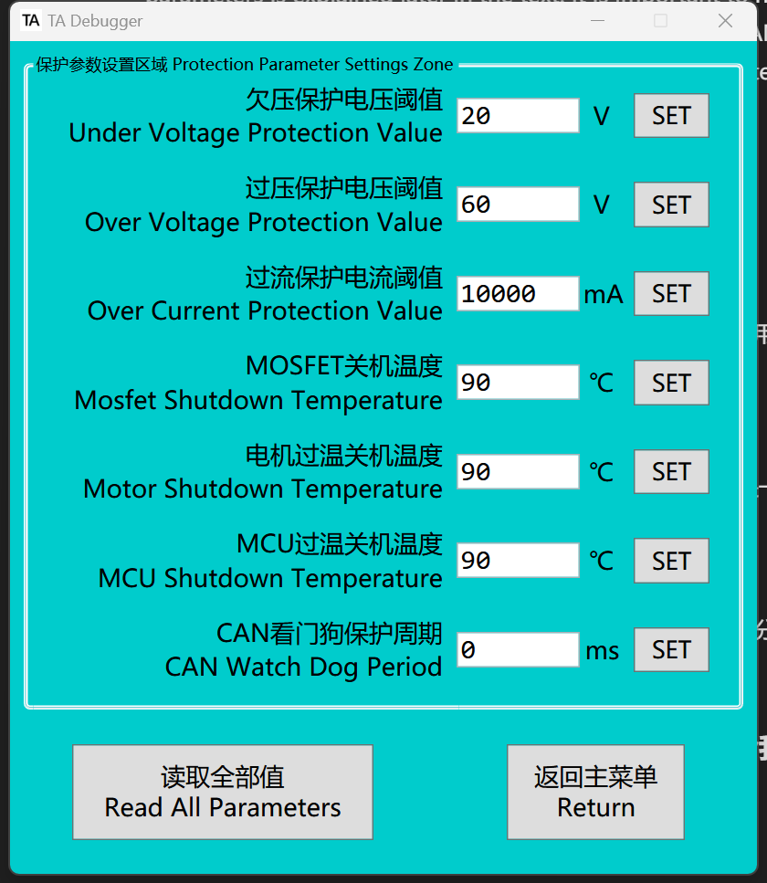
Protection Parameter Settings
Users can configure various motor protection parameters, though adjustments are generally unnecessary as these are pre-configured before shipment. However, users may modify the protection parameters based on specific application requirements.
Reset
- When need to switch modes, a reset is required. In TA-Debugger, return=reset. After sending the reset command, the driver will immediately restart. During the restart, the red LED will light up briefly, then turn off, followed by the blue LED staying solid.
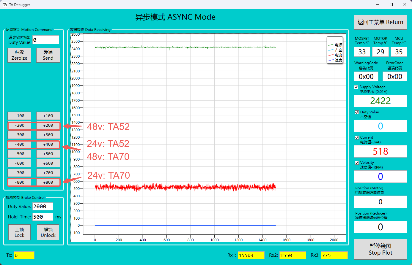
ASYNC Mode
- Asynchronous mode is used during production for calibrating the motor-side encoder, allowing the motor to rotate without relying on sensors.
📌
Under normal actuator conditions, users are advised to avoid using this mode. This mode is primarily provided for remote encoder calibration.
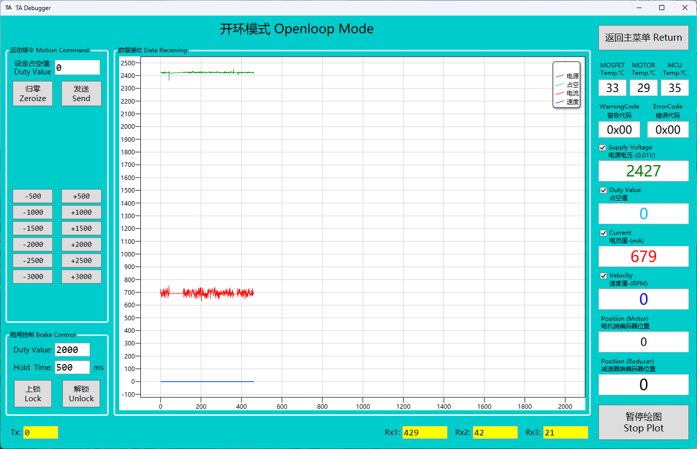
Open-Loop Mode
- Open-loop mode is used during production for calibrating the reducer-side encoder, enabling simple motor rotation.
📌
Under normal actuator conditions, users are advised to avoid using this mode. This mode is primarily provided for remote encoder calibration.
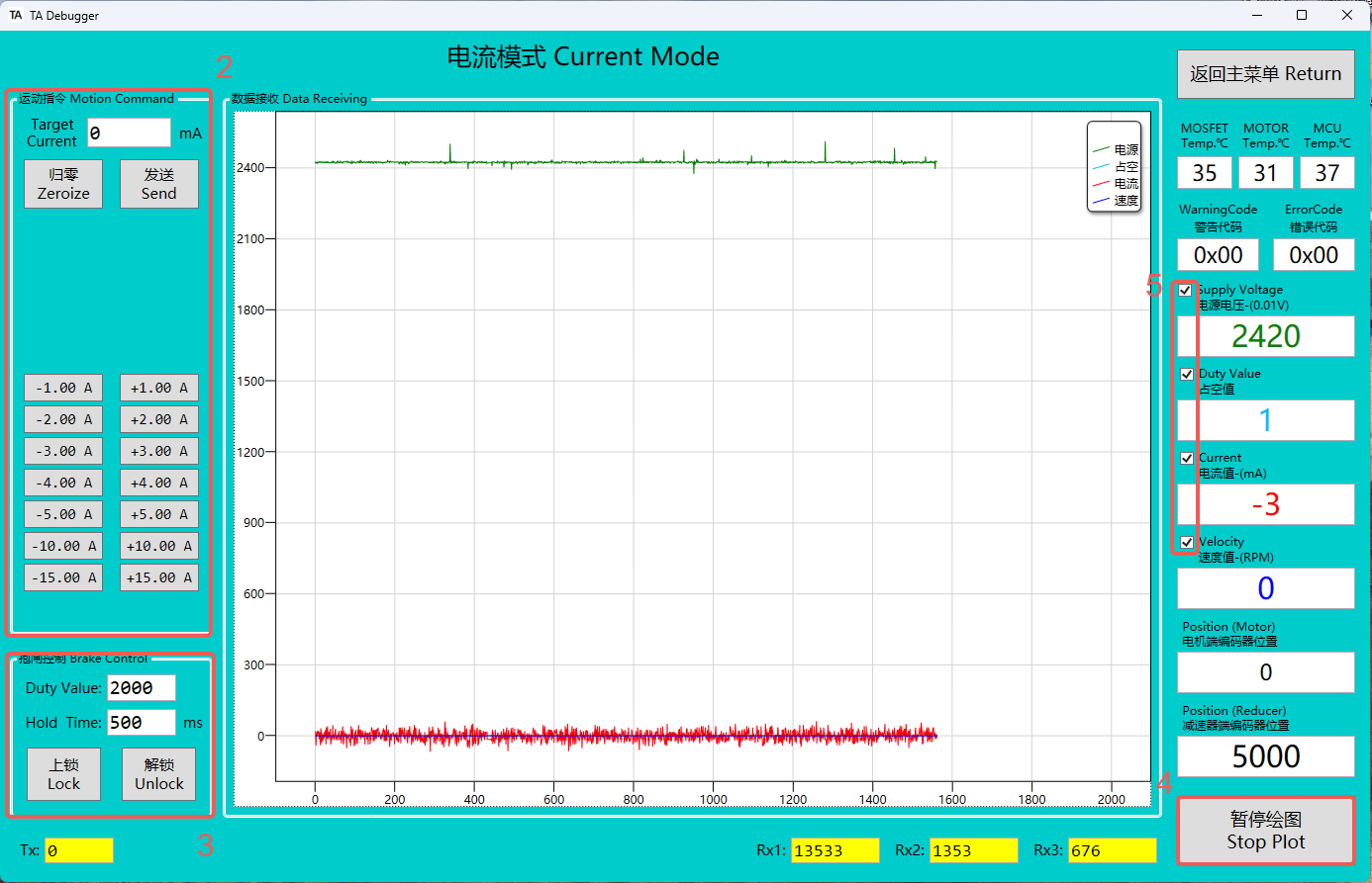
Current Mode
-
After entering current mode, the LED status indicator changes from blue to green, and the brake is automatically released.
-
This area is the control section for current mode. Users can drive the motor by pressing buttons or entering specific current values. When debugging in current mode, please start with a small current and gradually increase it; otherwise, it may cause danger.
-
This area allows manual control of the brake's lock and release states,please do not modify the pwm and duration value.
-
Clicking Stop Plotting will pause the generation of the real-time curve graph.
-
By checking or unchecking the box, you can decide whether to display the corresponding state curve graph.
-
Supports modification via Flash memory (one-time modification) as well as via RAM (real-time modification) for the current loop PID settings in this mode. The specific configuration methods can be found in the "Control Frame" section below.
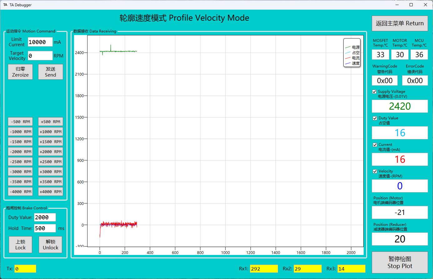
Profile-Velocity Mode
- After entering Profile-Velocity Mode, the LED status indicator changes from blue to green, and the brake is automatically released.
- It is possible to control both the current limit and the motor speed simultaneously. When the current limit is set too low, it may prevent the motor from reaching the desired speed, as the current is insufficient to provide the necessary torque, thus limiting the motor's rotational speed. Therefore, when setting the current limit, it is important to ensure that it meets the motor's load requirements at the target speed to avoid situations where the speed cannot reach the expected value.
- Supports modification via Flash memory (one-time modification) as well as via RAM (real-time modification) for the acceleration/deceleration and current loop, speed loop PID settings in this mode. The specific configuration methods can be found in the "Control Frame" section below.
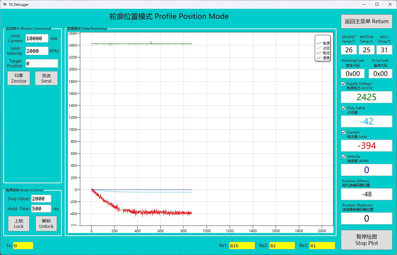
Profile-Position Mode
- Profile position mode has a built-in trajectory planning function, and any position update commands sent before the previous trajectory planning is completed will be ignored.
- After entering Profile-Position Mode, the LED status indicator changes from blue to green, and the brake is automatically released. The reducer end automatically returns to the zero position (this behavior can be disabled in the motor parameter settings).When exiting, the brake will automatically lock.
- The current limit, motor speed, and gearbox position (can be modified to motor position) can be controlled simultaneously. If the current limit is too low, the motor may not reach the set speed, so ensure the current limit meets the load requirements.
- The acceleration and deceleration parameters in this mode can be adjusted. These parameters share a common data structure with the profile speed mode. Both Flash-based modifications (one-time change) and RAM-based modifications (real-time change) are supported. The detailed configuration method can be found in the Control Frame section.
- The PID parameters for the current loop, speed loop, and position loop in this mode can be modified via Flash memory (one-time modification) or RAM (real-time modification). The detailed configuration method can be found in the Control Frame section below.
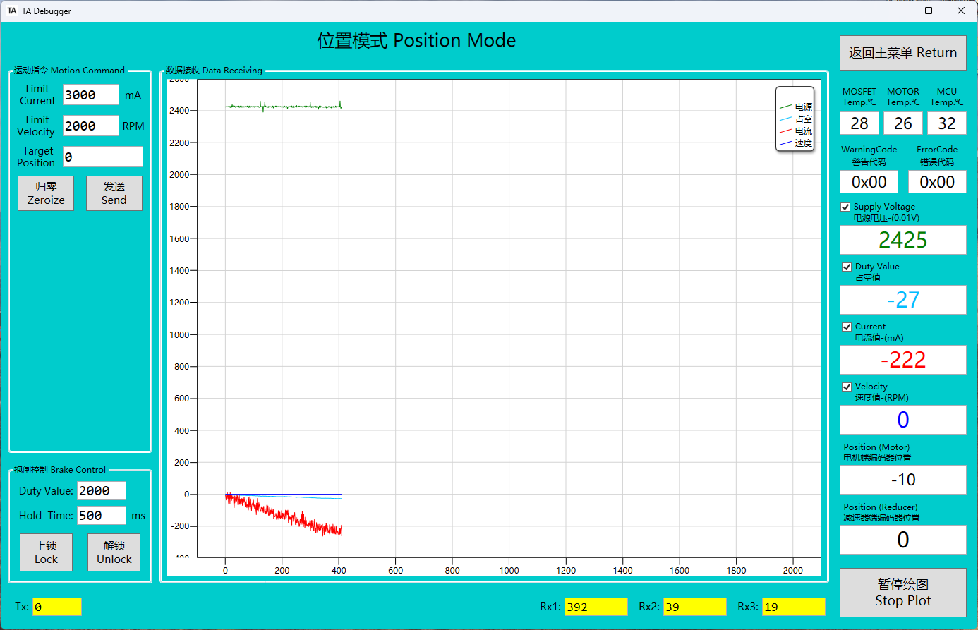
Position Mode
- This position mode uses a three-loop architecture, consisting of position loop, velocity loop, and current loop. Unlike the profile position mode, this mode does not include built-in trajectory planning, allowing high-frequency position updates, but requires external trajectory planning.
- Upon entering position mode, the LED indicator changes from blue to green, the brake is automatically released, and the reducer returns to position 0 (this auto-reset can be disabled in the motor parameter settings). When exiting the mode, the brake will automatically lock.
- The current limit, motor speed, and gearbox position (can be modified to motor position) can be controlled simultaneously. If the current limit is too low, the motor may not reach the set speed, so ensure the current limit meets the load requirements.
- The acceleration and deceleration parameters in this mode can be adjusted. These parameters share a common data structure with the profile speed mode. Both Flash-based modifications (one-time change) and RAM-based modifications (real-time change) are supported. The detailed configuration method can be found in the Control Frame section.
- The PID parameters for the current loop, speed loop, and position loop in this mode can be modified via Flash memory (one-time modification) or RAM (real-time modification). The detailed configuration method can be found in the Control Frame section below.
MIT Mode
-
After entering MIT mode, the LED status indicator changes from blue to green, and the brake is automatically released. The reducer end automatically returns to the zero position (this behavior can be disabled in the motor parameter settings).When exiting, the brake will automatically lock.
-
The MIT mode is a specialized control mode developed by MIT, primarily used for precise torque and motor control applications. It allows for advanced control of motor performance.
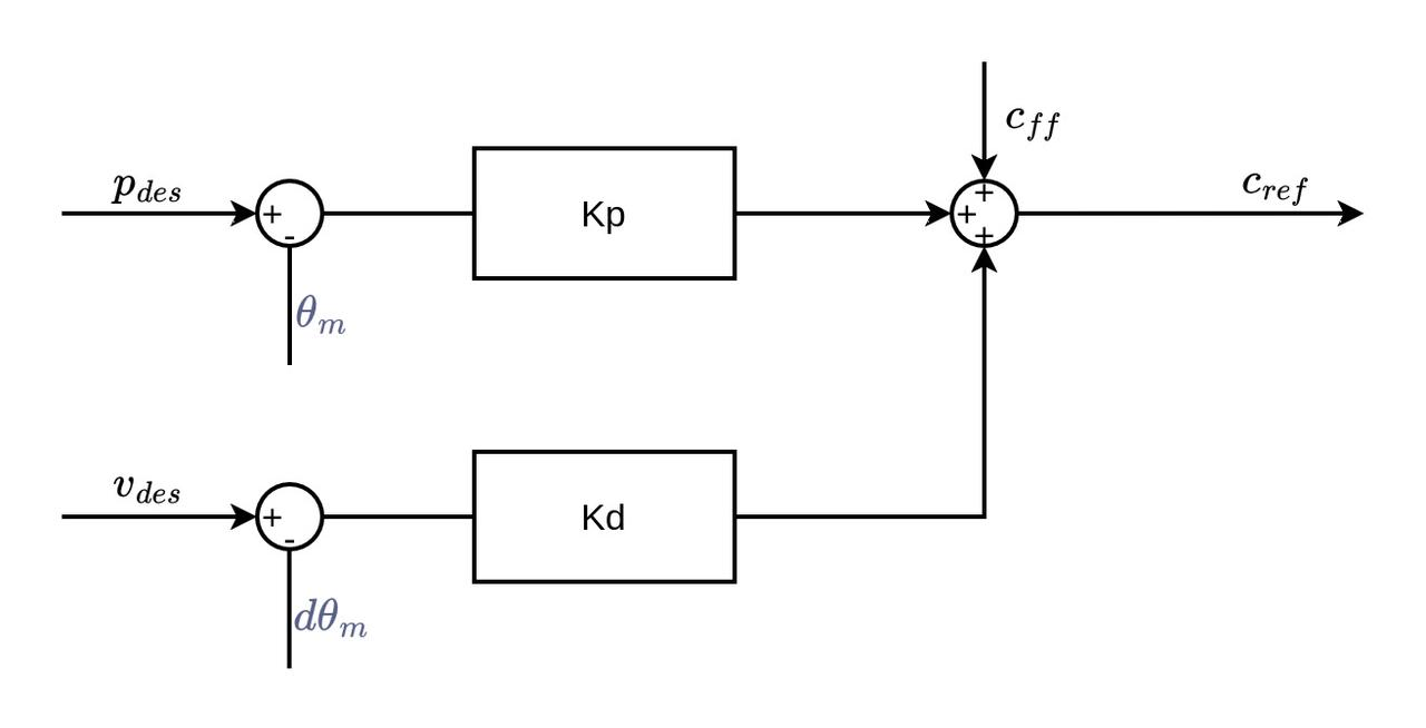
-
In MIT mode, two separate CAN frames need to be sent: one frame contains the motor's current, speed, and the position information of the reducer (which can be changed to the motor-end position in the motor parameter settings), and the other frame contains the MIT_Kp and MIT_Kd values. The specific method for setting these parameters can be found in the "Control Frame" section below.It is also affected by the current limit value set in the motor parameter settings.

-
Simple Example of MIT Control Mode
Set Position to 0°
Set Position to 360°
Set Velocity to 1000rpm
Set Current to 3A
current
0
0
0
3000
ma
velocity
0
0
1000
0
rpm
position
0
65536
0
0
Kp
0.09
0.09
0
0
Kd
13.1
13.1
30
0