Acutator Debugger Software User Guide
1.Installation Instructions
- Download the software.
- Install and run it on a Windows machine.
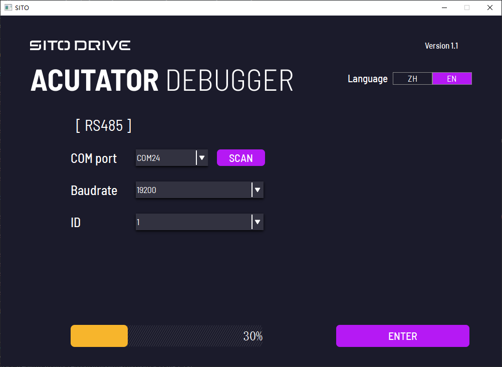
2. Initial Interface
Steps:
-
Select the Correct Serial Port.
-
Click the SCAN button to start scanning. This will scan all baud rates for motors with IDs ranging from 1 to 10. Detected motor IDs and baud rates will be displayed automatically in the dropdown menu. Users can also manually select the baud rate and ID.
-
After entering the correct baud rate and ID, click the ENTER button at the bottom-right corner to access the mode selection interface.
Additional Information:
-
After clicking the SCAN button, a progress bar will appear at the bottom. When the scan completes, a message box will appear:
-
If successful:
baudrate {motor baudrate}, ID {motor ID}.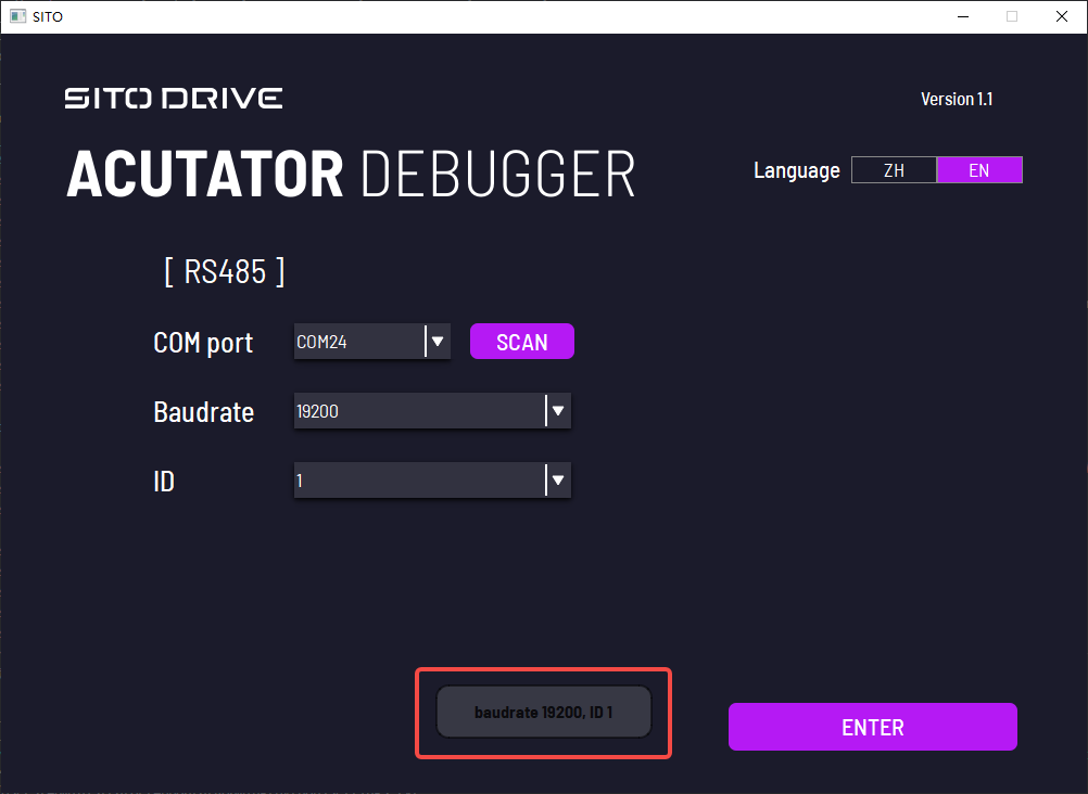
-
If no motor is found:
No motor found.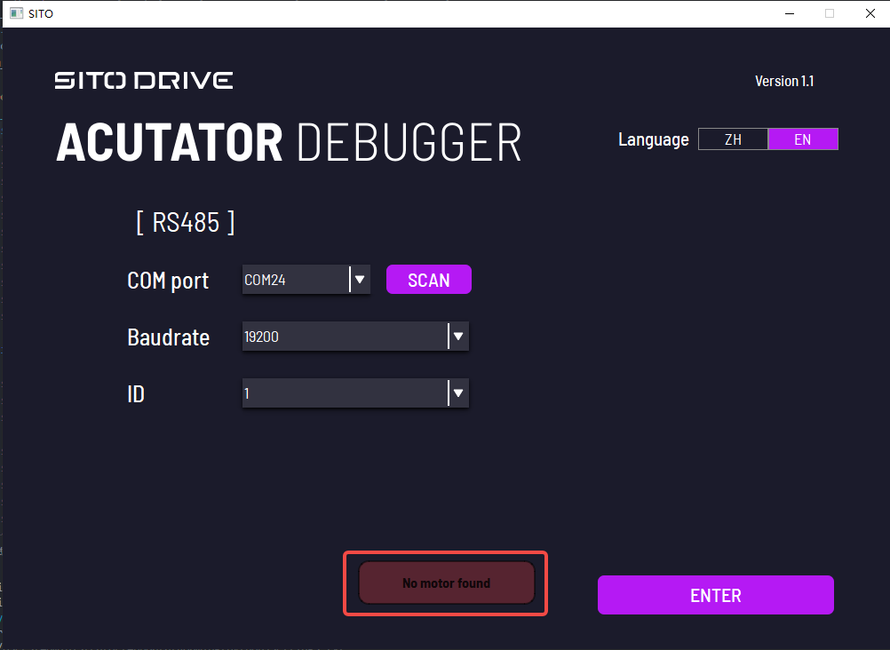
-
-
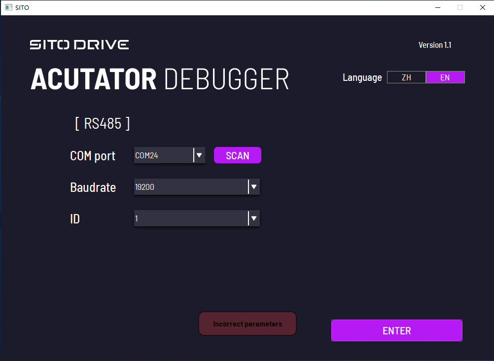
If the serial port, baud rate, or ID is incorrect, clicking the ENTER button will show an "Incorrect parameters" message box.
-
Click the Language button at the top-right corner to toggle between Chinese and English.
3. Mode Selection Interface
Steps:
- Choose the desired mode. The selected mode box will turn purple.
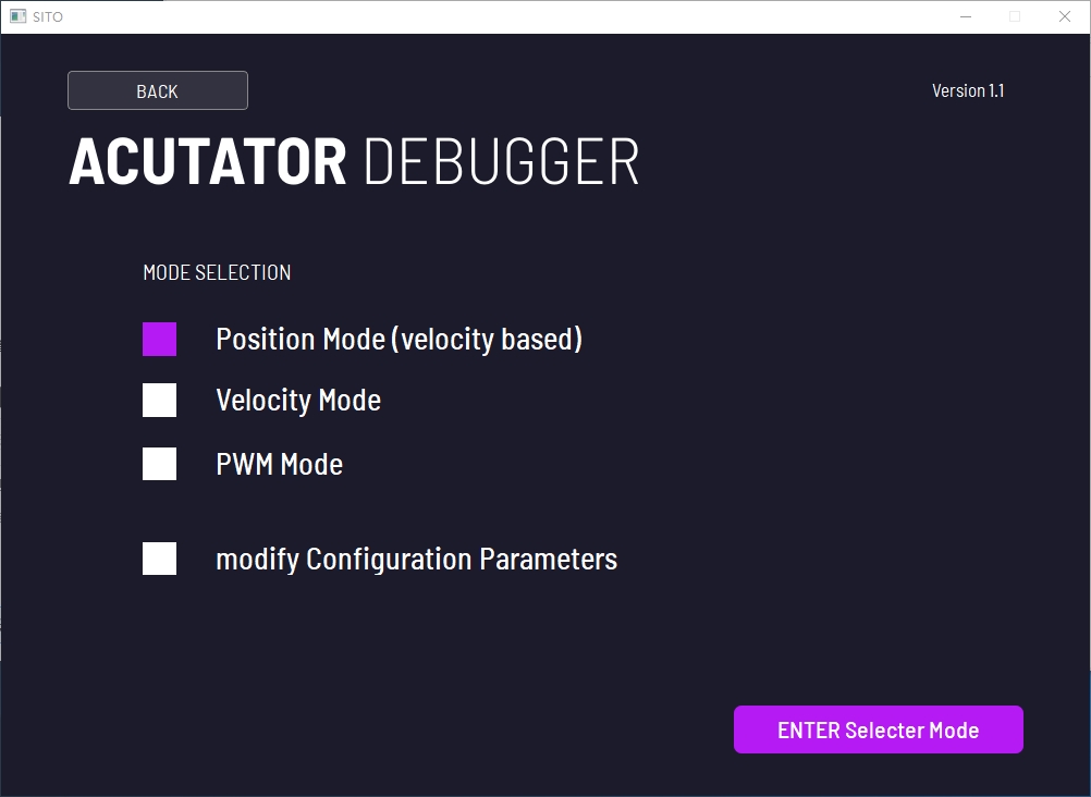
- Click the ENTER Selected Mode button to enter the corresponding mode interface.
Additional Information:
- Click the BACK button at the top-left corner to return to the home page.
4. Position Mode
Note: When entering Position Mode, the motor will first return to zero.
The interface consists of four sections:
-
Actuator Status
-
Parameter Settings
-
Position Control (Relative Position)
-
Position Control (Absolute Position)
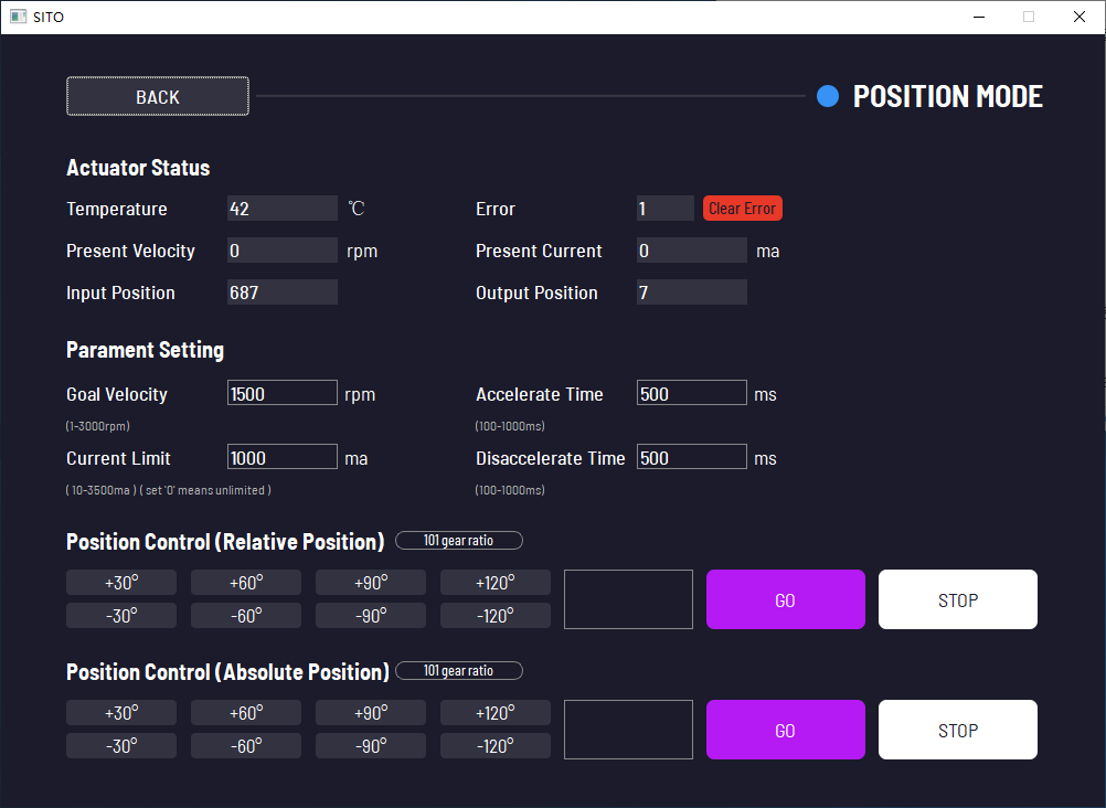
4.1. Actuator Status
Displays the motor's:
- Temperature
- Fault status
- Present Velocity
- Present Current
- Input position
- Output position
If a motor fault occurs (fault status ≠ 0), the Clear Error button will turn red. Click it to clear the fault.
4.2. Parameter Settings
Allows users to set the following:
- Target speed
- Current limit
- Acceleration time
- Deceleration time
To modify parameters:
- Enter the new value in the input box next to the parameter name.
- Press Enter on your keyboard to confirm.
4.3. Position Control (Relative Position)
- Changes the motor's relative position (angles are cumulative with each click).
- Unit: degrees (°).
- Actions:
- Click one of the eight buttons on the left to adjust position.
- Enter a custom angle (up to two decimal places) in the input box next to the buttons, then click the GO button to execute.
- To stop the motor, click the STOP button.
- The button next to "Position Control (Relative Position)" switches the motor's reduction ratio between 101 and 51.
4.4. Position Control (Absolute Position)
-
Changes the motor's absolute position relative to its origin.
-
Unit: degrees (°).
-
Actions:
- Similar to Relative Position Control, you can use the left buttons or input a custom angle, then click GO to execute.
- To stop the motor, click the STOP button.
-
The button next to "Position Control (Absolute Position)" switches the motor's reduction ratio between 101 and 51.
-
Click the BACK button at the top-left corner to return to the mode selection interface.
5. Speed Mode
The interface consists of:
-
Actuator Status
-
Speed Control
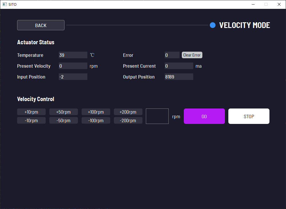
5.1. Actuator Status
Displays the motor's:
- Temperature
- Fault status
- Present Velocity
- Present Current
- Input position
- Output position
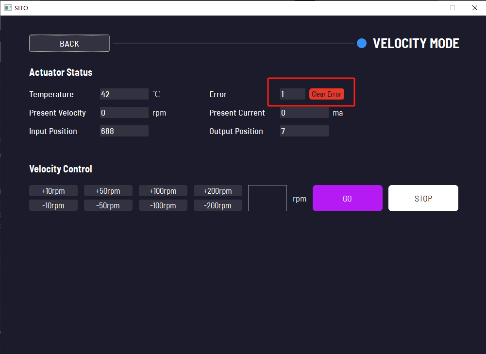
If a motor fault occurs (fault status ≠ 0), the Clear Error button will turn red. Click it to clear the fault.
5.2. Speed Control
-
Adjusts the motor's speed.
-
Actions:
- Use the buttons on the left to increase/decrease speed (values are cumulative).
- Enter a custom speed in the input box (whole numbers only, unit: rpm), then click the GO button to execute.
- To stop the motor, click the STOP button.
-
Click the BACK button at the top-left corner to return to the mode selection interface.
6. PWM Mode
The interface consists of:
-
Actuator Status
-
PWM Control
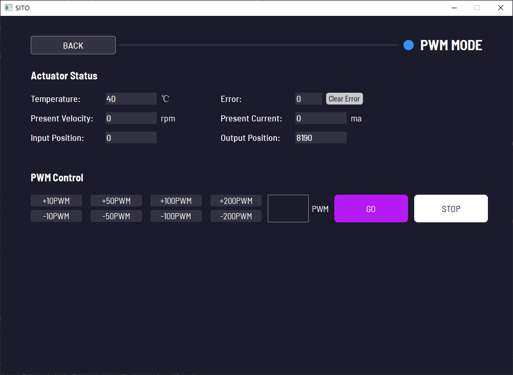
6.1. Actuator Status
Displays the motor's:
- Temperature
- Fault status
- Present Velocity
- Present Current
- Input position
- Output position
If a motor fault occurs (fault status ≠ 0), the Clear Error button will turn red. Click it to clear the fault.
6.2. PWM Control
-
Adjusts the motor's PWM value.
-
Actions:
- Use the buttons on the left to increase/decrease the PWM value (values are cumulative).
- Enter a custom PWM value (whole numbers only, unit: pwm) in the input box, then click the GO button to execute.
- To stop the motor, click the STOP button.
-
Click the BACK button at the top-left corner to return to the mode selection interface.
7. Configuration Parameters Interface
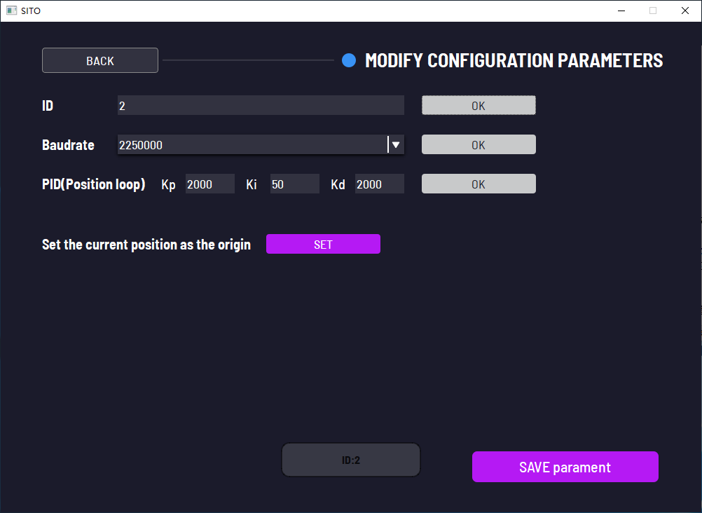
This interface allows modification of the following parameters:
- Motor ID:
- Enter the target ID in the ID input box, then click OK.
- Baud Rate:
- Select the target baud rate from the dropdown menu, then click OK.
- Position Loop PID:
- Enter the target Kp, Ki, and Kd values in their respective input boxes, then click OK.
- Motor Origin Position :
- Move the motor to the desired position, then click the SET button.
Additional Steps:
- After modifying parameters, click the SAVE Parameters button at the bottom-right corner.
- Exit the software and reboot the motor.