Getting Started
Hardware Preparation
- TA Series Actuator
-
USB-CAN Converter: If using a different USB-CAN converter, it must comply with the "CAN Protocol and Serial Frame Conversion" rules described below; otherwise, it will not function properly.
-
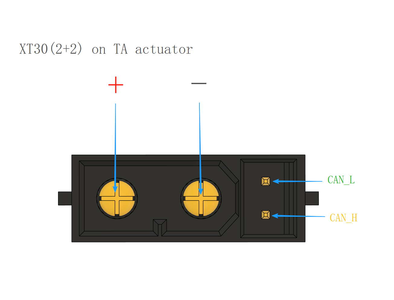
Power and Communication Adapter Cable: XT30 (2+2) male connector is used on the actuator, with 2 pins for power and 2 pins for signal.It is recommended to use twisted pair cables for signal transmission.
-
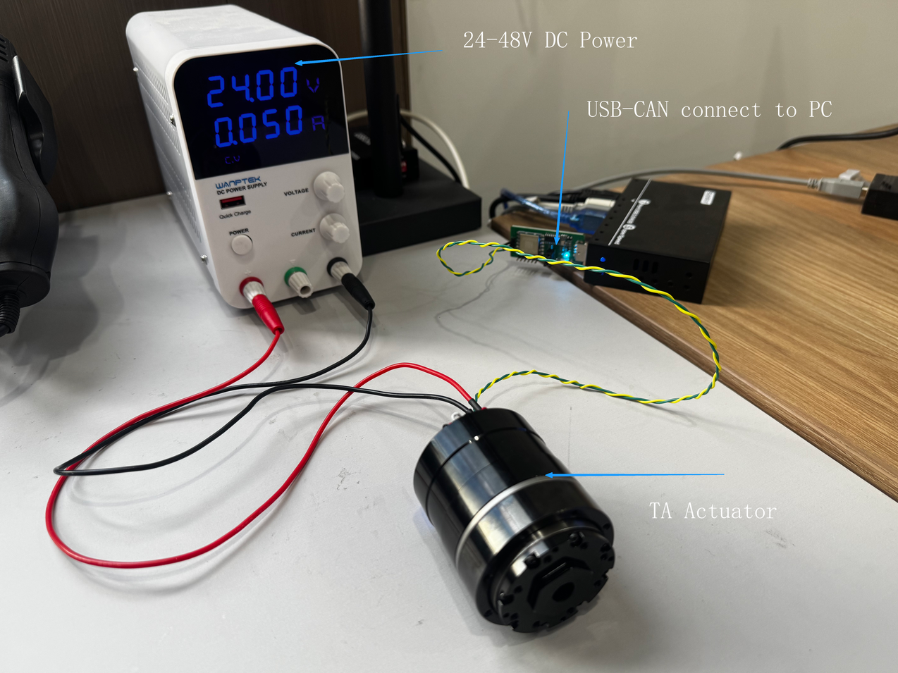
24-48V DC Regulated Power Supply: For driving a single TA actuator, a 5A bus current is sufficient.
Power-On
- Both the TA52 and TA70 can be directly powered by 24-48V. However, with a 24V power supply, the motor speed of the TA14 can only reach around 1000 RPM. For higher speeds, please use a 48V power supply for the TA14.
- When power is turned on, the actuator's LED will briefly light up red, then turn off, and finally stay blue, indicating the driver has rebooted and returned a Feedback0 packet with the serial number and firmware version date.
- If use 24V, check the static current of the DC power supply. Under normal conditions, the current for TA52 and TA70 in this state should be around 50mA. If there is a significant difference (greater than 10mA), stop usage immediately and contact the relevant technical personnel.
- Due to variations in different power supplies, a ±2mA difference may occur. It is recommended to use a 0.001A precision regulated power supply to monitor the current. This is because a 0.01A precision power supply has significant errors and is not reliable for sampling small current values.
USB-CAN Converter
- Connect the actuator → USB-CAN converter → computer in the correct wiring sequence.
- Open Device Manager to check if the USB-CAN converter is recognized. If it is not recognized, it may be due to a missing CH340 driver. Please download the CH340 driver from the official website, install it, and reconnect the USB-CAN converter before checking again.

Download TA-Debugger
-
TA-Debugger is the debugging software for TA actuators. This software is feature-rich, user-friendly, and currently only supports Windows. Support for Linux and macOS will be added in future updates.

- The software can be downloaded from the official link or by contacting the relevant technical personnel to obtain the latest version.
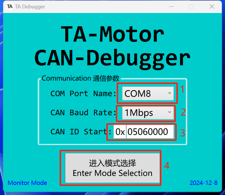
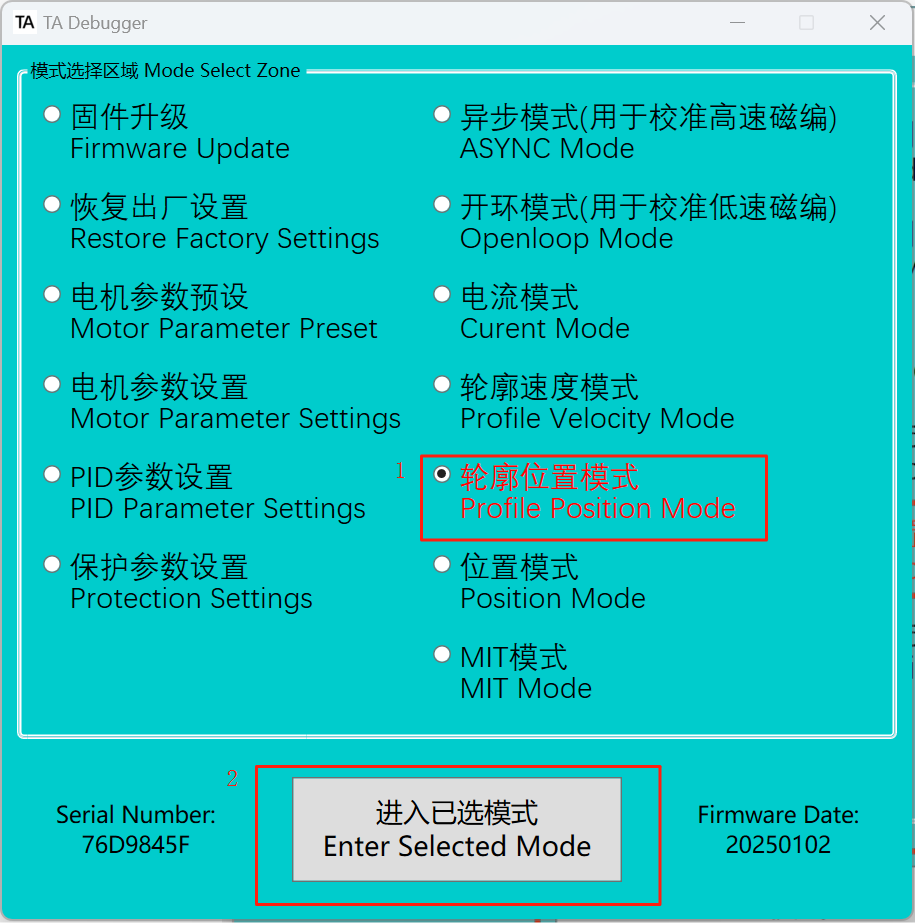
Open TA-Debugger
- Select the correct COM port.
- Select the baud rate. Currently, only 1M is available. More baud rate options will be added through firmware updates in the future.
- Select the correct CAN ID. The default CAN ID from the factory is
0x05060000. - Please enter the mode selection. The date in the bottom right corner indicates the software version date.
Check the Connection
- Check if the serial number and firmware version date are displayed. If displayed, communication is successful; if empty, communication has failed. Please check the wiring and ensure the power is on.
检查是否显示序列号和固件版本日期。若有显示,则通信成功;若为空,则通信失败,请检查接线和电源。
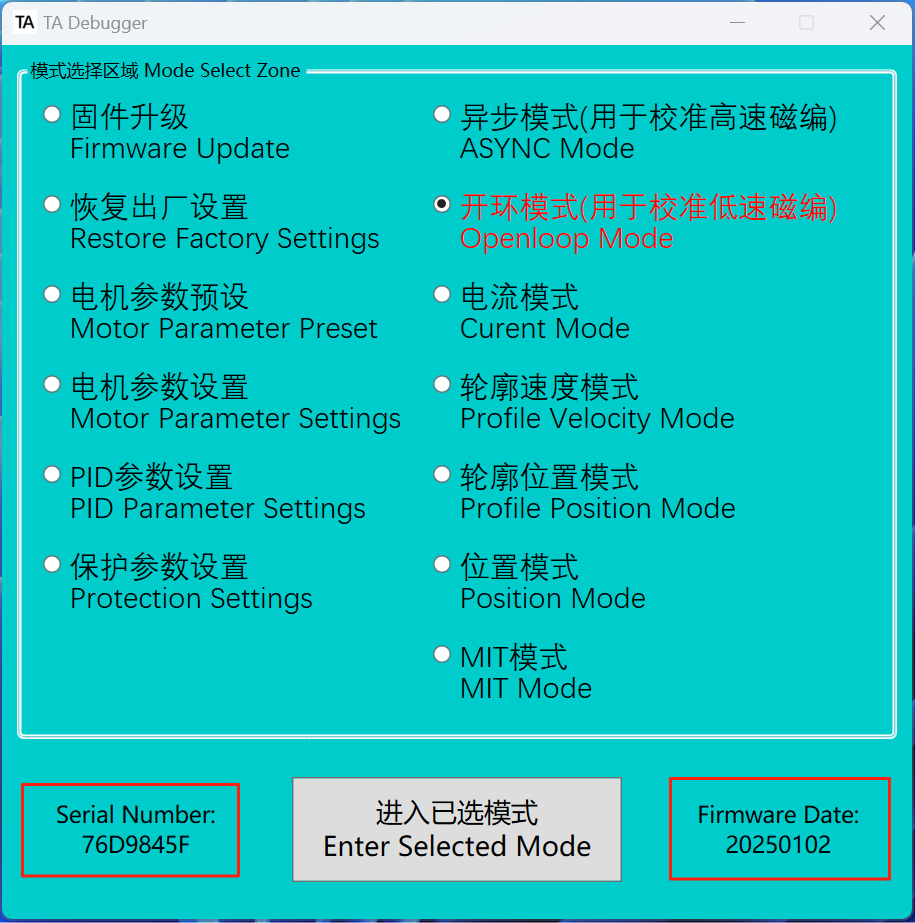
Profile-Position Mode
-
Next, we will activate the actuator using the Profile Position Mode as an example. This mode allows simultaneous control of the motor's phase current limit, speed, and the reducer's position (which can be switched to motor position via motor parameter settings). The Profile Position Mode includes a built-in trajectory planning function, where any updated position commands sent before the completion of the current trajectory will be disregarded.
-
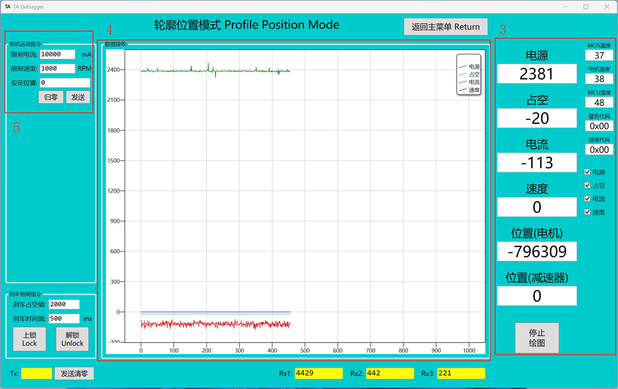
Please enter the selected mode. Once entered, the brake will automatically release, and the LED indicator will turn solid green
-
Real-time actuator status information.
-
Real-time information of voltage, PWM, current, and velocity curves.
-
Control area of this mode
-
After entering profile position mode, the reducer will automatically return to 0 by default. The user can also choose not to auto-reset to 0 in the motor settings.
-
Try entering the position 5000 in this area and click Send. The reducer end will then move to position 5000.
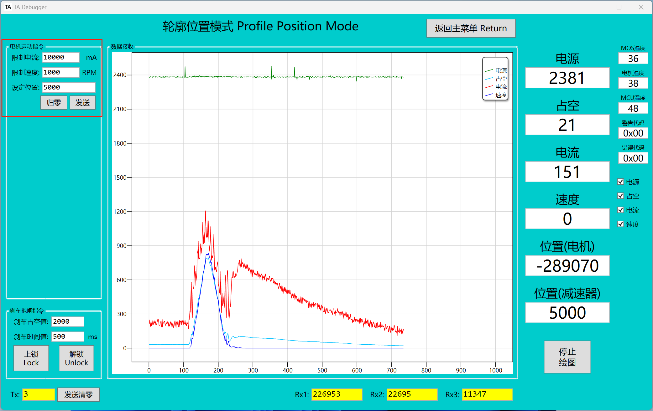 ✅
✅The value for one full rotation of the reducer end is 16 bits = 65536